


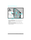
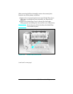
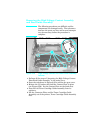

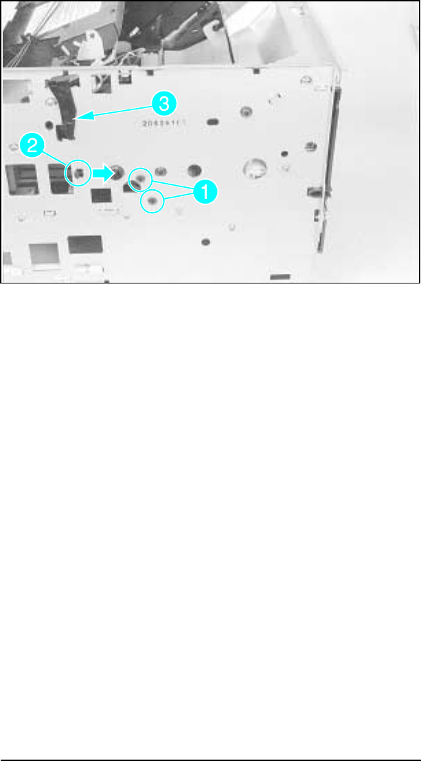
5 From the left side of the printer, remove the (1) or (2) black,
self-tapping screw(s) that holds the Left Toner Cartridge
Guide Plate (see Figure 6-55, callout 1).
6 Release the guide plate latch (see Figure 6-55, callout 2).
7 Remove the Laser Shutter Pivot Pin from its seat in the Left
Toner Cartridge Guide Plate (see Figure 6-55, callout 3).
These two steps (5 & 6) are required for the next stage of the
HVCP removal process.
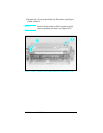
Figure 6-55 Left Toner Cartridge Guide Plate Screw
6-66 Removal and Replacement