


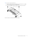
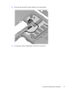
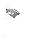
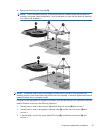
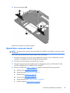
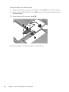
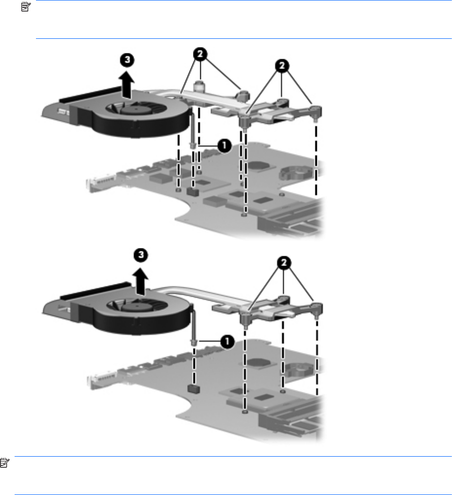
4. Remove the fan/heat sink assembly (3).
NOTE: Due to the adhesive quality of the thermal material located between the fan/heat sink
assembly and system board components, it may be necessary to move the fan/heat sink assembly
from side to side to detach it.
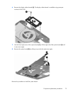
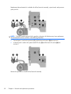
NOTE: The thermal material must be thoroughly cleaned from the surfaces of the fan/heat sink
assembly and the system board each time the fan/heat sink assembly is removed. Replacement thermal
material locations vary by computer model.
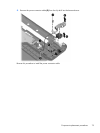
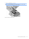
Computer models equipped with a graphics subsystem with discrete memory have replacement thermal
material locations as shown in the following illustration:
●
Thermal paste is used on the processor (1) and the heat sink section (2) that services it
●
Thermal paste is used on the graphics subsystem chip (3) and the heat sink section (4) that
services it
●
A thermal pad is used on the system board PCH chip (5) and the heat sink section (6) that
services it
Component replacement procedures
81