


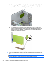
Connect a media card reader USB 3.0 cable with a USB 3.0 to USB 2.0 adapter to the USB 2.0
connector on the system board labeled MEDIA.
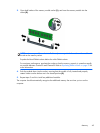
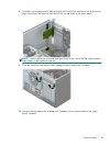
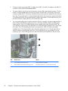
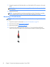
The power cable for the drives has two branches coming off the system board connector. The first
branch is a three-headed cable with the first connector routed to the 5.25-inch bay, the second
connector routed to the 3.5-inch bay, and the third (two-wire) connector routed to the slim optical
drive bay. The second branch is a three-headed cable with the first connector routed to the bottom
2.5-inch hard drive bay, the second connector routed to the middle 3.5-inch hard drive bay, and
the third connector routed to the top 3.5-inch hard drive bay.
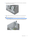
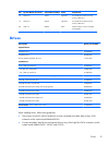
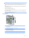
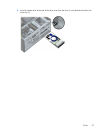
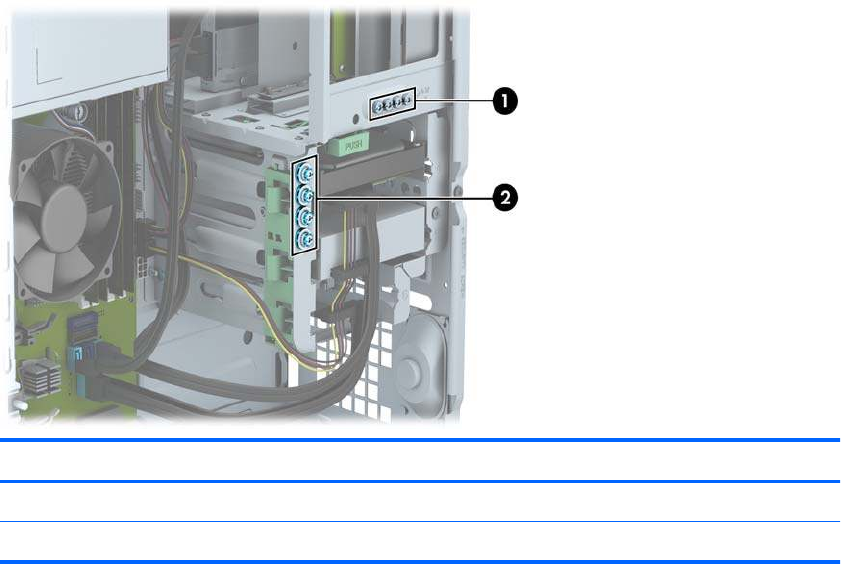
You must install guide screws to ensure the drive will line up correctly in the drive cage and lock in
place. HP has provided extra guide screws (four 6-32 silver and blue isolation mounting guide
screws and four silver 6-32 standard guide screws) installed on the side of the drive bays. The
6-32 isolation mounting screws are required for 3.5-inch hard drives installed in the 3.5-inch hard
drive bays. The 6-32 standard guide screws are required for a USB 3.0 media card reader
installed in the 3.5-inch optional drive bay. M3 metric guide screws for 5.25-inch optical drives
and M3 isolation mounting guide screws for 2.5-inch hard drives are not provided. If you are
replacing a drive, remove the guide screws from the old drive and install them in the new drive.
No. Guide Screw Device
1 Silver Standard 6-32 Guide Screws USB 3.0 Media Card Reader
2 Silver and Blue 6-32 Isolation Mounting Screws Secondary Hard Drive in 3.5-inch Hard Drive Bay
52 Chapter 5 Removal and replacement procedures: Tower (TWR)