


Hardware options installation 46
CAUTION: To prevent a server malfunction or damage to the equipment, do not add or remove
the capacitor pack while an array capacity expansion, RAID level migration, or stripe size
migration is in progress.
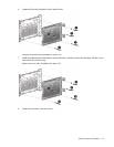
CAUTION:
After the server is powered down, wait for 30 seconds, and then check the amber LED
before unplugging the cable from the cache module. If the amber LED flashes after 30 seconds,
do not remove the cable from the cache module. The cache module is backing up data. Data will
be lost if the cable is detached when the amber LED is still flashing.
IMPORTANT: The capacitor pack might have a low charge when installed. If the pack does have
low charge a POST error message appears when the server is powered up, indicating that the
capacitor pack is temporarily disabled. No action is necessary. The internal circuitry
automatically recharges the capacitors and enables the capacitor pack. This process might take
up to 4 hours. During this time, the cache module functions properly but without the performance
advantage of the capacitor pack.
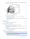
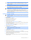
Installing a storage controller
IMPORTANT: For additional installation and configuration information, see the documentation
that ships with the option.
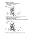
To install the component:
1. Power down the server (on page 15).
2. Disconnect the power cord from the AC source.
3. Disconnect the power cord from the server.
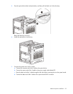
4. Remove the chassis cover (on page 19).
5. Install the storage controller ("Expansion board options" on page 55).
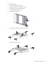
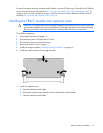
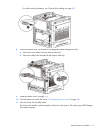
6. Connect all necessary internal cables to the storage controller. For internal drive cabling information,
see "Storage cabling (on page 60)."
7. If you intend to use an FBWC module and capacitor pack, install these options now ("Installing the
FBWC module and capacitor pack" on page 47).
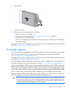
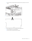
8. Open the front bezel (on page 16).
9. Install the drives ("Drive options" on page 43).
CAUTION: To prevent improper cooling and thermal damage, do not operate the server unless
all bays are populated with either a component or a blank.
10. Close the front bezel.
11. Install the chassis cover (on page 19).
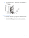
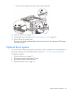
12. Connect the power cord to the server ("Connecting the power cord" on page 28).
13. Connect all necessary external cables to the storage controller. For more information on these cabling
requirements, see the documentation that ships with the option.
14. Press the Power On/Standby button.
The server exits standby mode and applies full power to the system. The system power LED changes
from amber to green.