


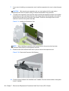
remove the four silver and blue 6-32 isolation mounting guide screws from the old hard drive and
install them in the new hard drive.
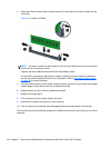
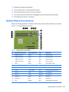
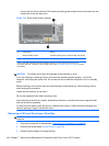
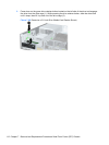
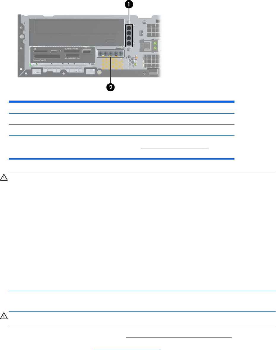
Figure 7-15 Extra Guide Screw Locations
No. Guide Screw Device
1 Black M3 Metric Screws All Drives (except primary and secondary hard drives)
2 Silver 6-32 Standard Screws Secondary Hard Drive
There are at total of five extra silver 6-32 standard screws. Four are used as guide screws for a
secondary hard drive. The fifth is used for bezel security (see
Front Bezel Security on page 95 for more
information).
CAUTION: To prevent loss of work and damage to the computer or drive:
If you are inserting or removing a drive, shut down the operating system properly, turn off the
computer, and unplug the power cord. Do not remove a drive while the computer is on or in standby
mode.
Before handling a drive, ensure that you are discharged of static electricity. While handling a drive,
avoid touching the connector.
Handle a drive carefully; do not drop it.
Do not use excessive force when inserting a drive.
Avoid exposing a hard drive to liquids, temperature extremes, or products that have magnetic fields
such as monitors or speakers.
If a drive must be mailed, place the drive in a bubble-pack mailer or other protective packaging and
label the package “Fragile: Handle With Care.”
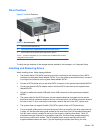
Removing a 5.25-inch Drive from a Drive Bay
CAUTION: All removable media should be taken out of a drive before removing the drive from the
computer.
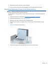
1. Prepare the computer for disassembly (Preparation for Disassembly on page 92).
2. Remove the access panel (
Access Panel on page 93).
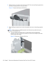
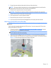
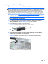
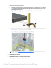
3. Rotate the drive cage to its upright position.
108 Chapter 7 Removal and Replacement Procedures Small Form Factor (SFF) Chassis