


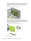
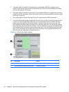
●
The power cable for the SATA optical drives is a two-headed cable this is plugged into the
system board with the first connector routed to the top 5.25-inch bay and the second connector
routed to the bottom 5.25-inch bay.
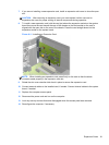
●
The power cable for the SATA hard drives is a two-headed cable this is plugged into the system
board with the first connector routed to the bottom 3.5-inch bay and the second connector routed
to the top 3.5-inch bay.
●
The system does not support Parallel ATA (PATA) optical drives or PATA hard drives.
●
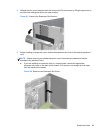
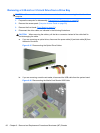
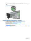
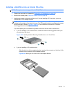
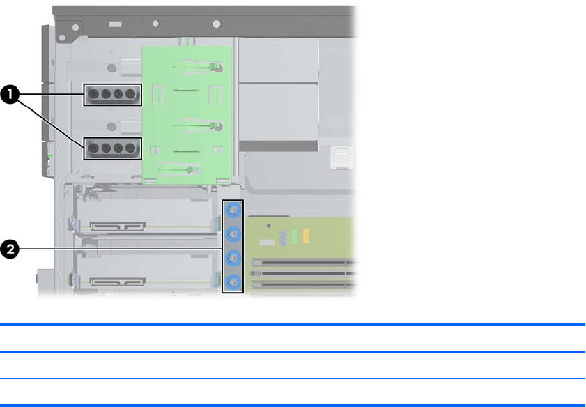
You must install guide screws to ensure the drive will line up correctly in the drive cage and lock
in place. HP has provided extra guide screws for the drive bays (four 6-32 isolation mounting
guide screws and eight M3 metric guide screws), installed on the side of the drive bays. The
6-32 isolation mounting screws are required for a secondary hard drive. All other drives (except
the primary hard drive) use M3 metric screws. The HP-supplied metric screws are black and the
HP-supplied isolation mounting screws are silver and blue. If you are replacing the primary hard
drive, you must remove the four silver and blue 6-32 isolation mounting guide screws from the
old hard drive and install them in the new hard drive.
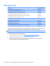
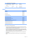
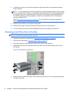
Figure 6-13 Extra Guide Screw Locations
No. Guide Screw Device
1 Black M3 Metric Screws All Drives (except hard drives)
2 Silver and Blue 6-32 Isolation Mounting Screws Secondary Hard Drive
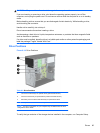
64 Chapter 6 Removal and Replacement Procedures Microtower (MT) Chassis