


populated with the least amount of memory describes the total amount of memory assigned to
dual channel and the remainder is assigned to single channel. For optimal speed, the channels
should be balanced so that the largest amount of memory is spread between the two channels.
If one channel will have more memory than the other, the larger amount should be assigned to
Channel A. For example, if you are populating the sockets with one 2-GB DIMM, and one 1-GB
DIMM, Channel A should be populated with the 2-GB DIMM, and Channel B should be
populated with the 1-GB DIMM. With this configuration, 2 GB will run as dual channel and 1 GB
will run as single channel.
●
In any mode, the maximum operational speed is determined by the slowest DIMM in the system.
The system will automatically operate in single channel mode, dual channel mode, or flex mode,
depending on how the DIMMs are installed.
Removing Memory Modules
CAUTION: You must disconnect the power cord and wait approximately 30 seconds for the power
to drain before adding or removing memory modules. Regardless of the power-on state, voltage is
always supplied to the memory modules as long as the computer is plugged into an active AC outlet.
Adding or removing memory modules while voltage is present may cause irreparable damage to the
memory modules or system board.
The memory module sockets have gold-plated metal contacts. When upgrading the memory, it is
important to use memory modules with gold-plated metal contacts to prevent corrosion and/or
oxidation resulting from having incompatible metals in contact with each other.
Static electricity can damage the electronic components of the computer or optional cards. Before
beginning these procedures, ensure that you are discharged of static electricity by briefly touching a
grounded metal object.
When handling a memory module, be careful not to touch any of the contacts. Doing so may damage
the module.
1. Prepare the computer for disassembly (Preparation for Disassembly on page 49).
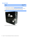
2. Remove the access panel (
Access Panel on page 50).
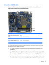
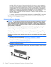
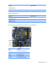
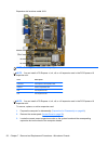
3. Locate the memory module sockets on the system board.
WARNING! To reduce risk of personal injury from hot surfaces, allow the internal system
components to cool before touching.
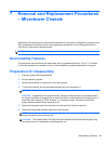
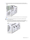
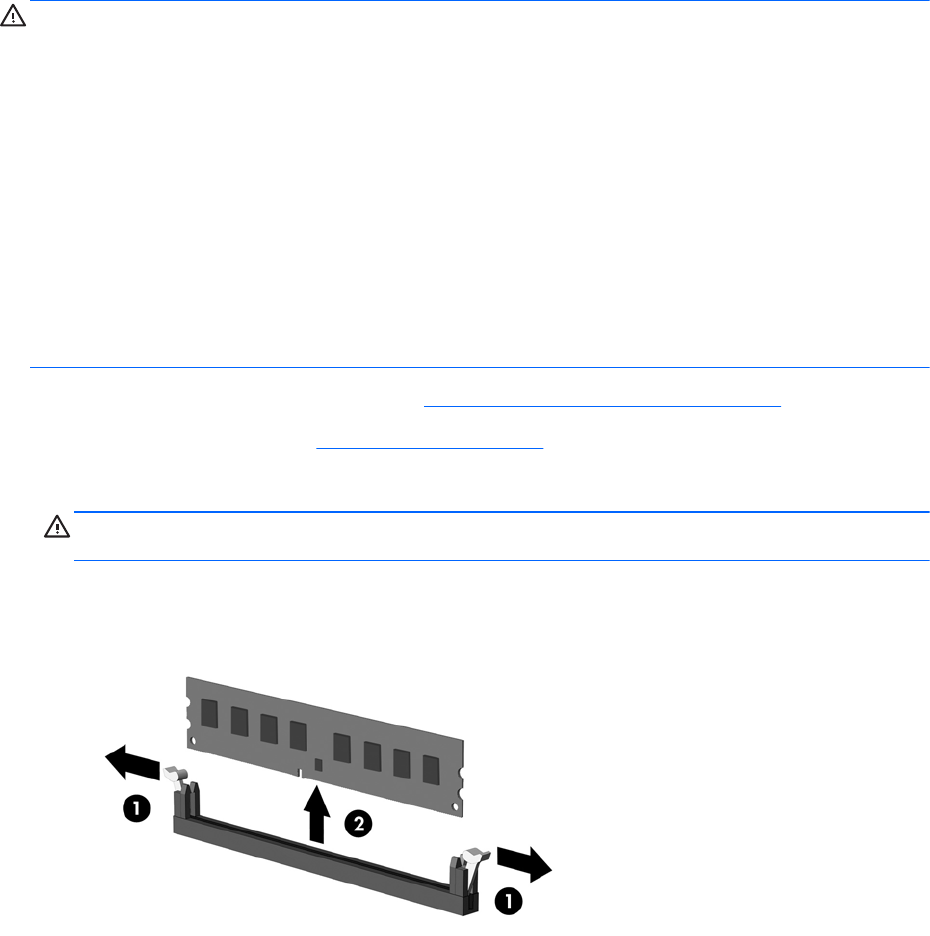
4. Open both latches (1) of the memory module socket , and remove the memory module from the
socket (2).
54 Chapter 7 Removal and Replacement Procedures – Microtower Chassis