


Description Spare part number
G530, 2.4 GHz, 2-MB L3 cache (use only in 3400/3410/3500 models) 665117-001
G440, 1.6 GHz, 1-MB L3 cache (use only in 3400/3410 models without Windows 8) 665467-001
AMD A-Series Advanced Processing Units (APU); not for use in Brazil:
A10-5800K, 3.8 GHz, 4-MB L2 cache; Radeon HD7660D graphics core (use only in 3515 models) 701408-001
A10-5700, 3.4 GHz, 4-MB L2 cache; Radeon HD7660D graphics core (use only in 3515 models) 701407-001
A8-5600K, 3.6 GHz, 1-MB L2 cache; Radeon HD7560D graphics core (use only in 3515 models) 701412-001
A8-5500, 3.2 GHz, 1-MB L2 cache; Radeon HD7560D graphics core (use only in 3515 models) 701411-001
A8-3870 (3.0 GHz, 4-MB L2 cache, 65W; Radeon HD6550D graphics core) for use only in HP Pro
3505 models
671611-001
A8-3820 (2.5 GHz, 4-MB L2 cache, 65W; Radeon HD6550D graphics core) for use only in HP Pro
3505 models
671610-001
A8-3800 (2.4 GHz, 4-MB L2 cache, 65W; Radeon HD6550D graphics core) 667723-001
A8-3550 (2.8 GHz, 4-MB L2 cache, 65W; Radeon HD6550D graphics core) 667721-001
A6-5400K, 3.6 GHz, 1-MB L2 cache; Radeon HD7540D graphics core (use only in 3515 models) 701410-001
A6-3670 (2.7 GHz, 4-MB L2 cache, 100W; Radeon HD6550D graphics core) for use only in HP
Pro 3505 models
671609-001
A6-3650 (2.6 GHz, 4-MB L2 cache, 100W; Radeon HD6550D graphics core) 667722-001
A6-3620 (2.2 GHz, 4-MB L2 cache, 65W; Radeon HD6350D graphics core) 671608-001
A6-3600 (2.1 GHz, 4-MB L2 cache, 65W; Radeon HD6530D graphics core) 667724-001
A4-5300, 3.4 GHz, 1-MB L2 cache; Radeon HD7480D graphics core (use only in 3515 models) 701409-001
A4-3420 (2.8 GHz, 4-MB L2 cache, 65W; Radeon HD6530D graphics core) for use only in HP Pro
3505 models
680937-001
A4-3400 (2.7 GHz, 4-MB L2 cache, 65W; Radeon HD6530D graphics core) 667725-001
E2-3200 (2.4 GHz, 1-MB L2 cache, 65W; Radeon HD6370D graphics core) 667726-001
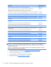
CAUTION: Do NOT handle the pins in the processor socket. These pins are very fragile and
handling them could cause irreparable damage. Once pins are damaged it may be necessary to
replace the system board.
CAUTION: The heat sink must be installed within 24 hours of installing the processor to prevent
damage to the processor’s solder connections.
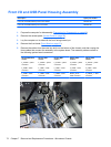
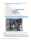
1. Prepare the computer for disassembly (Preparation for Disassembly on page 49).
2. Remove the access panel (
Access Panel on page 50).
3. Lay the computer on its side with the rear facing toward you.
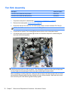
4. Remove the fan sink
Fan Sink Assembly on page 78).
80 Chapter 7 Removal and Replacement Procedures – Microtower Chassis