


Removal and replacement procedures 37
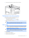
Recovering data from the flash-backed write cache
If the server fails, use the following procedure to recover data temporarily stored in the FBWC.
CAUTION: Before starting this procedure, read the information about protecting against
electrostatic discharge ("Preventing electrostatic discharge" on page 21).
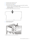
1. Perform one of the following:
o Set up a recovery server using an identical server model. Do not install any internal drives or FBWC
in this server. (HP recommends this option.)
o Find a server that has enough empty drive bays to accommodate all the drives from the failed server
and that meets all the other requirements for drive and array migration.
2. Power down the failed server ("Power down the server" on page 23).
3. Transfer the drives from the failed server to the recovery server.
4. Perform one of the following:
o If the array controller has failed, remove the cache module and capacitor pack from the failed array
controller, and install the cache module and capacitor pack on an identical array controller model
in the recovery server.
o If the server has failed, remove the controller, cache module, and capacitor pack from the failed
server, and install the controller, cache module, and capacitor pack in the recovery server.
5. Power up the recovery server. If there was data in the cache at the time of the controller or server failure,
a 1792 POST message appears, stating that valid data was flushed from the cache. This data is now
stored on the drives in the recovery server. You can now transfer the drives (and controller, if one is
used) to another server.
If the drives are migrated to different drive positions or there are volumes present in the recovery server,
a 1724 POST message appears, stating that logical drive configuration has been updated
automatically.
Front I/O module assembly
To remove the component:
1. Power down the server (on page 23).
2. Disconnect the power cord from the AC source.
3. Disconnect the power cord from the server.
4. Remove the front bezel (on page 25).
5. Remove the chassis cover (on page 26).
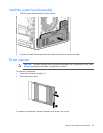
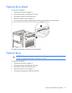
6. If installed, remove the optical drive ("Optical drive" on page 33).
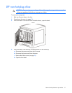
7. If installed, remove the expansion board ("Expansion board" on page 47).
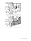
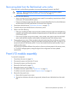
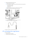
8. Remove the front panel cover:
a. Remove the front panel cover screws.
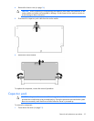
b. Starting from the bottom side and moving upward, release the rear side latches from their metal
tabs.