


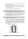
Registers Format • 15
Address: BASE + 0h
Attribute: read only
Data Format:
for 12-bits PCI-9111DG
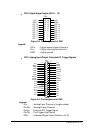
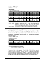
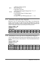
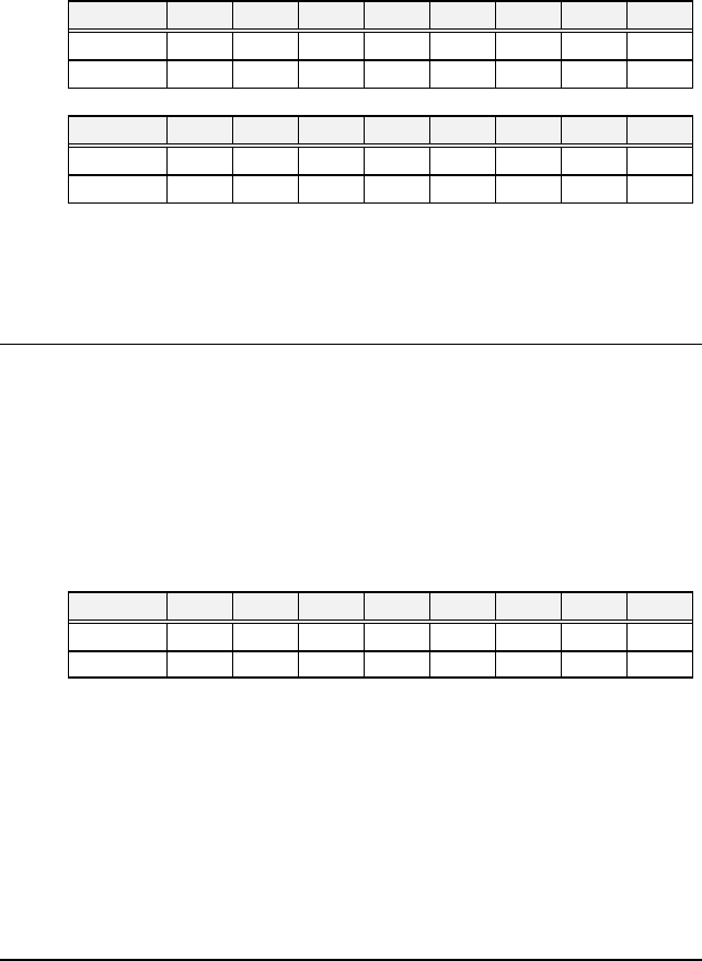
Bit 7 6 5 4 3 2 1 0
BASE+0h AD3 AD2 AD1 AD0 CH3 CH2 CH1 CH0
BASE+1h AD11 AD10 AD9 AD8 AD7 AD6 AD5 AD4
for 16-bits PCI-9111HR
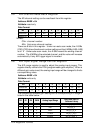
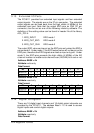
Bit 7 6 5 4 3 2 1 0
BASE+0h AD7 AD6 AD5 AD4 AD3 AD2 AD1 AD0
BASE+1h AD15 AD14 AD13 AD12 AD11 AD10 AD9 AD8
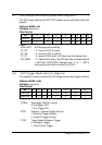
AD15 ~ AD0: Analog to digital data. AD11 is the Most Significant Bit
(MSB) of PCI-9111DG while AD15 is the MSB of
PCI-9111HR. AD0 is the Least Significant Bit (LSB).
CH3 ~ CH0: A/D channel number from which the data is derived.
3.4 A/D Channel Control Register
The PCI-9111 provides 16 single-ended analog input channel. The
channel control register is used to set the A/D channels to be converted.
Under non-auto scanning mode, the register sets the channel number for
conversion. Under auto-scanning mode, the register sets the ending
channel number.
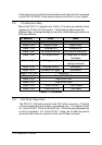
Address: BASE + 6h
Attribute: write only
Data Format:
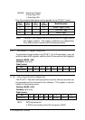
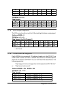
Bit 7 6 5 4 3 2 1 0
BASE+6h CN7 CN6 CN5 CN4 CN3 CN2 CN1 CN0
BASE+7h -- -- -- -- -- -- -- --
Where:
CNn: Multiplexer channel number.
CN7 is MSB, and CN0 is LSB.
There are 8 bits in this register. The 4 LSBs (CN0~CN3) are used to
select on-board multiplexer. Usually, only the 4 LSBs are used and 16
input channels can be selected. However, if there is an extension board
which can provide extension ability to 256 analog input channels, the 4
MSBs (CN4~CN7) can also be used to control the extension board.