


18 • Registers Format
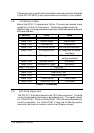
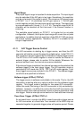
ASCAN: Auto Scan Control
0: Auto Scan OFF
1: Auto Scan ON
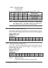
Only the modes listed below can be applied on the PCI-9111 card:
Bit 3
PTRG
Bit 2
EITS
Bit 1
TPST
Bit 0
ASCAN
Mode Description
0/1 0 0 0/1 Software Trigger & Polling
0/1 0 1 0/1 Timer Pacer Trigger
0/1 1 X 0/1 External Trigger
Note: The bits in this register can only control the A/D trigger source
and trigger method. The trigger conditions are independent
from data transfer method and interrupt generation.
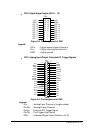
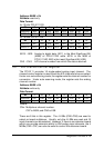
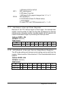
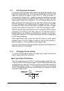
3.9 Software Trigger Register
To generate a trigger pulse to the PCI-9111 for A/D conversion, you just
write any data to this register, and then the A/D converter will be triggered.
Address: BASE + 0Eh
Attribute: write only
Data Format:
Bit 7 6 5 4 3 2 1 0
BASE+0Eh X X X X X X X X
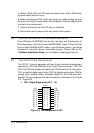
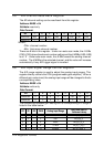
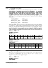
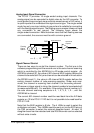
3.10 Interrupt Control Register
The PCI-9111 has dual interrupt systems and two interrupt sources can
be generated and be checked by the software. This register is used to
select the interrupt sources.
Address: BASE + 0Ch
Attribute: write only
Data Format:
Bit 7 6 5 4 3 2 1 0
BASE+0Ch X X X X X FFEN ISC1 ISC0
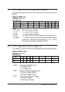
ISC0: IRQ0 signal select
0: IRQ on the ending of the AD conversion (EOC)