


2-8
Installing the Series 5400zl Switches
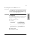
Installation Procedures
Installing the Series 5400zl
Switches
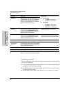
Installation Location
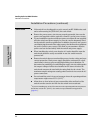
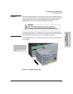
Before installing the switch, plan its location and orientation relative to other
devices and equipment:
■ In the front of the switch, allow at least 7.6 cm (3 inches) of space for the
twisted-pair and fiber-optic cabling.
■ In the back of the switch, allow at least 10.2 cm (4 inches) of space for the
power cord and cooling.
■ On the sides of the switch, leave at least 7.6 cm (3 inches) for cooling.
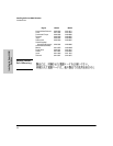
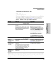
10-GbE SR Multimode fiber-optic cable designed for
Gigabit Ethernet: 62.5/125 μm (core/cladding)
diameter or 50/125 μm, 850 nm, low metal
content, complying with the ITU-T G.652 and
ISO/IEC 793-2 Type B1 standards.
■ 62.5 μm cable:
• 160 Mhz/km = 2-26 meters
• 200 Mhz/km = 2-33 meters
■ 50 μm cable:
• 400 Mhz/km = 2-66 meters
• 500 Mhz/km = 2-82 meters
• 2000 Mhz/km = 2-300 meters
10-GbE LR 9/125 μm (core/cladding) diameter, 1480 nm,
low metal content, single mode fiber-optic
cables, complying with the ITU-T G.652 and
ISO/IEC 793-2 Type B1 standards.
single-mode cable: 2-10 kilometers
10-GbE ER 9/125 μm (core/cladding) diameter, 1480 nm,
low metal content, single mode fiber-optic
cables, complying with the ITU-T G.652 and
ISO/IEC 793-2 Type B1 standards.
single-mode cable: 2-30 kilometers (40
kilometers, on an engineered fiber optic link
that meets standards in the specification).
Note: Conditioning patch cord cables are not supported on 10-GbE.
OMC CX4 Fiber
Optical Media
Converter
12 fiber 50/125 μm (core/cladding) diameter,
multimode Fiber ribbon cable. 12 fiber 62.5/125
μm (core/cladding) diameter, multimode Fiber
ribbon cable is also supported.
50 μm cable or 62.5 μm cable: 100 meters
Copper Cables
Port Type Cable Specifications Connector Type
CX4 Speed 3.125Gbx4
(Cables compliant with the 802.3ak standard)
CX4
Port Type Cable Type Length Limits