


2-17
Installing the Series 5400zl Switches
Installation Procedures
Installing the Series 5400zl
Switches
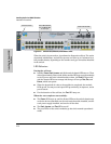
• If the ports are connected to active network devices, the Link LEDs
stay on and the Mode LEDs behave according to the mode selected.
In the default mode (Activity), the Mode LEDs should flicker showing
network activity on the port.
• If the ports are not connected to active network devices, the LEDs
will stay off.
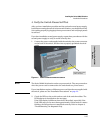
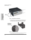
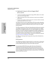
5.Mount the Switch
After the modules and optional power supply are installed and you have
verified the switch passes self test, you are ready to mount the switch in a
stable location. The Series 5400zl Switches can be mounted in these ways:
■ in a rack or cabinet
■ on a horizontal surface
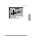
Rack or Cabinet Mounting
The Series 5400zl Switches are designed to be mounted in any EIA-standard
19-inch telco rack or in an equipment cabinet such as a server cabinet. If you
are installing the switch in an equipment cabinet, read the following “Equip-
ment Cabinet Note” on page 2-17.
Equipment
Cabinet
Note
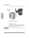
If you are installing the switch in an equipment cabinet, in place of the
12-24 screws supplied with the switch, use the clips and screws that came with
the cabinet. Plan which four holes you will be using in the cabinet and install
all four clips and partially install the two bottom screws, as described in step
2 on the previous page, before proceeding to step 3.
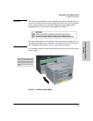
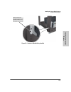
WARNING For safe operation, please read the “Installation Precautions” on page
2-5 and page 2-6 before mounting the switch.
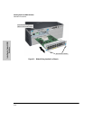
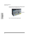
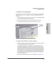
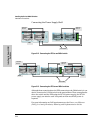
1. Use a #1 Phillips (cross-head) screwdriver and attach the mounting
brackets to the switch with the included 8-mm M4 screws.
For the Switch 5406zl, each bracket is attached with four screws as shown
in the following illustration.
Although these procedures show the 6-slot chassis, the procedures are
the same for the 12-slot chassis.