


US7070447-001, Rev 01
3-
1
Chapter 3
Hardware Diagnostics
The power and status LEDs indicate the general operations of the HiSpeed switch.
The HiSpeed switch provides transparent operation once it has been installed and
configured. If you suspect that it may be malfunctioning or causing a system
problem, check the status of the LEDs. Call Technical Support to report the
condition.
In addition to the built-in LEDs on the switch, there is an Integrated System
Diagnostic (ISD) software which tests the system to determine any hardware
failures. The system diagnostic’s focus is to help identify and verify major system
features and components such as the processor, memory, I/O devices, system
buses, packet switch and uplink interfaces on the switch.
The ISD software (
isd) and download instructions (isd.doc) are available on the
Hitachi anonymous FTP server, 204.48.18.63. If you are using a browser, type in
the following URLs to download the files:
ftp://ftp.hicam.hitachi.com/outgoing/isd
ftp://ftp.hicam.hitachi.com/outgoing/isd
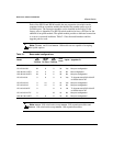
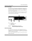
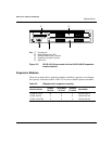
Observing LEDs
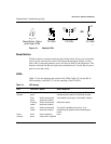
LEDs are located on each module and on the RJ-45 port connectors. Figure 3-1
shows the LED configurations,