


HiSpeed Switch Troubleshooting GUide
5-2
Doc Part Number, Version Number
Draft Level—Hitachi Confidential
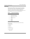
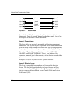
Figure 5-1. Network Media
Layers 1 through 3 define the network and how data is transferred across
the network. Layers 4 through 7 define how the data is used. Each of the
seven layers are described in more detail below.
La
y
er 1: Ph
y
sical La
y
er
This layer defines the physical, mechanical, and electrical connection to
the network. The Physical Layer is responsible for the actual transmission
of the bit stream on the medium. Electrical issues such as voltage, current,
frequency, and modulation techniques are governed by the physical layer.
Examples of Physical Layer specifications are cabling (10BASE5,
10BASE2, and 10BASE-T, 100BASE-T, etc. ), type and size of the
connector, number of pins in the connector, and the function of each of the
pins.
Examples of Physical Layer devices are repeaters and hubs.
La
y
er 2: Data Link La
y
er
This layer is responsible for assembling and disassembling data into
frames. The data link layer also checks the frames for error and flow
control to ensure for reliable data transfer. The Data Link is subdivided
into two separate sublayers: Media Access Control (MAC) and Logical
Link Control (LLC).
Layer 7
Layer 6
Layer 5
Layer 4
Layer 3
Layer 2
Layer 1
Layer 7
Layer 6
Layer 5
Layer 4
Layer 3
Layer 2
Layer 1
Application
Presentation
Session
Transport
Network
Data Link
Physical