


6 - 4
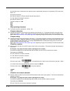
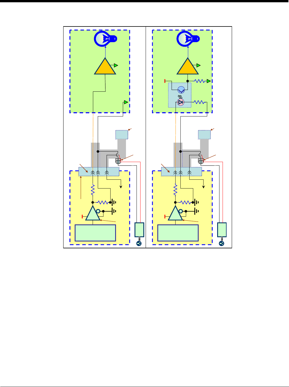
External Illumination Schematic
Standard Lamp Connection
On-Semiconductor
MC74VHC1GT125DF1G
Tri-state buffer or equivalent.
10K
Resistor
100 Ohm
0603 Resistor
+4.9V to
+5.2V
Scanner
Controller
Pin 15
3310 Scanner
Pin 6
Customer Device
Power Link
(Not on all cables)
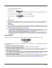
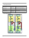
Lamp Connection Using Opto-Isolation Example
AC
Adapter
Customer
Ground
+5.2V
Scanner
Power
+5.2V
Opto-Isolator
Scanner Cable with
External Trigger and
Lamp Signals
Note: All connections for power, ground and scanner signals not shown for clarity.
Yellow Wire
Pin 11
To Customer
PC/Register
data connector
Customer
Power Supply
Black Wire
Lamp
Driver/Switch
Customer
Ground
On-Semiconductor
MC74VHC1GT125DF1G
Tri-state buffer or equivalent.
10K
Resistor
100 Ohm
0603 Resistor
+4.9V to
+5.2V
Scanner
Controller
Pin 15
3310 Scanner
Pin 6
Customer Device
Power Link
(Not on all cables)
AC
Adapter
Customer
Ground
+5.2V
Scanner
Power
+5.2V
Scanner Cable with
External Trigger and
Lamp Signals
Yellow Wire
Pin 11
To Customer
PC/Register
data connector
Black Wire
Lamp
Driver/Switch
Customer
Ground
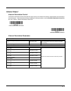
Please see External Illumination Parameters
for signal level information.
Note: All connections for power and
ground and communication not shown for
clarity. Additional details of the user
connector can be found in the
3310 User’s Guide.
User Connector (15 pin HD-22
pin size).
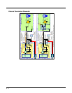
Please see External Illumination Parameters
for signal level information.
Note: All connections for power and
ground and communication not shown for
clarity. Additional details of the user
connector can be found in the
3310 User’s Guide.