


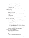


Connector Description
1 Digital video interface
(DVI) connector
Used to attach a digital monitor. This connector provides
the signals necessary to support the Display Power
Management Signaling (DPMS) standard.
2 S-Video connector Used to attach a television set that has a S-Video connector.
The S-Video cable (required to connect the television set to
the adapter) is a separately purchased item.
3 SVGA monitor
converter
Used to attach an analog SVGA monitor to the AGP DVI
connector. This SVGA converter is not used on this
machine type.
4 SVGA monitor
converter
Used to attach an analog SVGA monitor to the AGP DVI
connector.
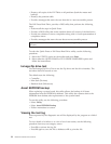
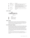
Audio adapter
Connector
1 MIDI/joystick connector
2 Audio line-out connector
3 Microphone connector
4 Audio line-in connector
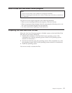
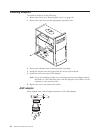
ADSL modem
Depending on how the user’s home or office is wired, the ADSL modem uses
either wires 2 and 5 or wires 3 and 4 of the telephone-line wall connector. Refer to
the label on the back of the ADSL modem and set the switch on the back of the
ADSL modem to match the wiring scheme. If you do not know which wiring
scheme to use, contact the user’s ADSL service provider.
Home PNA network adapter
Some models have a Home Phoneline Network Alliance network adapter with an
integrated V.90 modem. In addition to its modem function, this adapter enables the
user to use the telephone wiring in the user’s home for peer-to-peer networking.
To use the Home PNA Network adapter, the Intel AnyPoint software must be
installed from the Software Selections CD. Each computer on the home PNA
network must have a PNA network adapter and the associated software installed.
For information about using the PNA network adapter or the AnyPoint software,
refer to the AnyPoint documentation (provided with models that come with PNA
network adapters only).
Each computer on a home PNA network must be connected directly to a
telephone-line wall connector. If the user has more computers than telephone-line
wall connectors in a room, he/she must use a telephone splitter at the wall
connector.
Chapter 4. Installing Options 21