


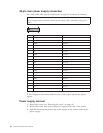
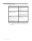
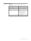
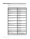
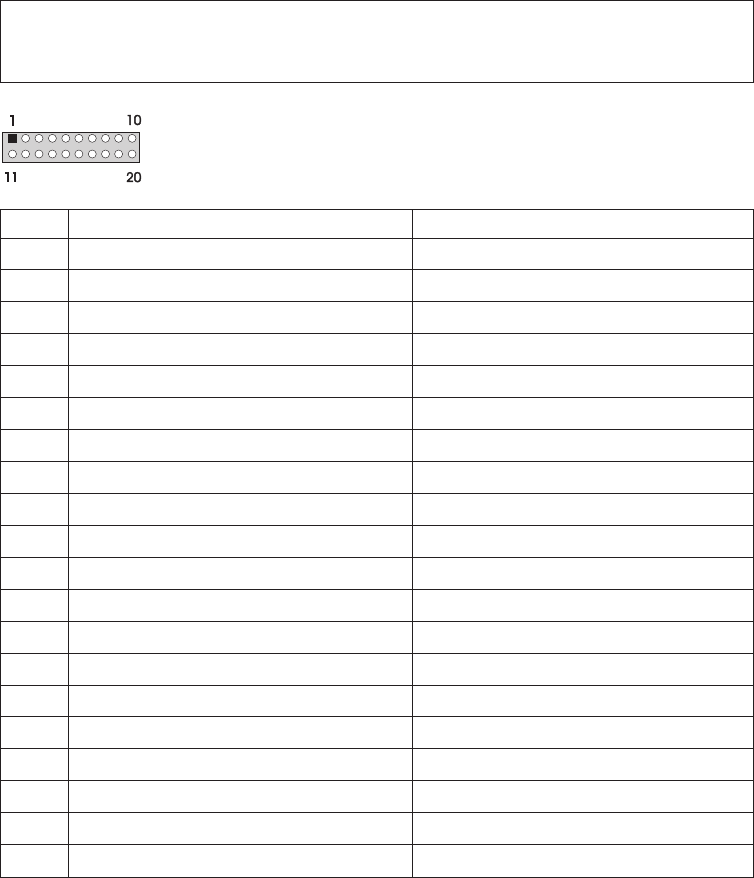
20-pin main power supply connection
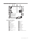
See “A40/A40P/A40i system board layout” on page 31 for connector locations.
Attention:
These voltages must be checked with the power supply cables connected to the system
board
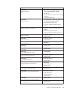
Pin Signal Function
1 3.3 V +3.3 V dc
2 3.3 V +3.3 V dc
3 COM Ground
4 5V +5Vdc
5 COM Ground
6 5V +5Vdc
7 COM Ground
8 POK Power Good
9 5VSB Standby Voltage
10 12 V +12 V dc
11 3.3 V +3.3 V dc
12 -12V -12Vdc
13 COM Ground
14 PS-ON DC Remote Enable
15 COM Ground
16 COM Ground
17 COM Ground
18 No voltage Not used
19 5V +5Vdc
20 5V +5Vdc
If the voltages are not correct, and the power cord is good, replace the power
supply.
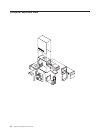
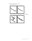
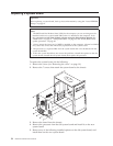
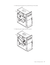
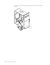
Power supply removal
1. Remove the cover (see “Removing the cover” on page 19).
2. Remove the screw that secures the power supply to the rear of the chassis.
3. Push the metal tab that secures the power supply to the chassis to release the
power supply.
36 Hardware Maintenance Manual