


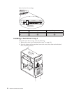
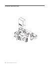
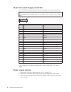

System board jumper settings
The following table contains the jumper setting information. (D) indicates the
default setting.
Clear CMOS/Flash Boot Block Recovery
Use the recovery jumper setting to Clear CMOS or to Flash Boot Block Recover.
Jumper Setting Description
CMOS Reset 2-3 CMOS Reset/Flash Recovery
Mode
1-2 (D) Normal Mode
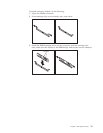
Note: The A40/A40P/A40i CMOS clear/recovery jumper pins are numbered as follows:
v Pin 1 is the farthest from the battery.
v Pins 2 and 3 are below pin 1, as seen in the System Board layout.
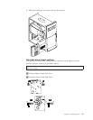
Processor Speed Settings
Processor speed for type 2251/6830/6831 computers are fixed and are determined
by the processor. There are no settings required.
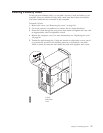
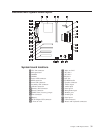
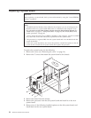
System board memory
The following matrix cross-references the name of the computer (printed on the
logo) and the size, speed, and type of memory modules supported in the
computer.
Installing memory
When installing DIMMs, the following rules apply:
v Fill each system memory connector sequentially, starting at DIMM 0.
v Use 3.3 V, 133 MHz, unbuffered, SDRAM non-parity DIMMs.
v Use only 64, 128 or 256 MB DIMMs in any combination.
32 Hardware Maintenance Manual