


3ware Escalade ATA RAID Controller Installation Guide
16
www.3ware.com
Hint:
While the ATA RAID Controller runs properly
in any PCI slot, not all slots give equal performance due
to the architecture of the PCI bus. In our laboratories, we
have noticed that the slots closest to the Accelerated
Graphics Port (AGP) or in the 64-bit PCI slot typically
give the best performance. Our card should fit in both
32-bit and 64-bit PCI slots with 5V as well as with 3.3V.
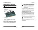
5 Line the ATA RAID Controller up so that all pins make proper
contact with the PCI slot pins when pushed into place. The black
end rail opposite the metal bracket may be removed if needed to
fit the ATA RAID Controller inside the chassis. The short 4-port
or 8-port Escalade ATA RAID Controller is keyed to ensure
proper installation in a full-sized PCI slot.
6 Ensure that the contacts will mate with both grooves in the slot.
Press down gently on the edge of the ATA RAID Controller
directly above the slot until it is fully seated.
7 Check that the ATA RAID Controller’s metal bracket covers the
hole in the case and secure the bracket with the screw that was
used to secure the filler bracket in step 4.
Connect the drives to the interface cables
1 Be sure to use the supplied cables. With the higher speeds of
UltraATA-133, UltraATA-100 and UltraATA-66, using quality
cables is important.
2 Before connecting your drives, check your drives’ jumper set-
ting. The range of settings provided vary by manufacturer as do
the method for adjusting them. Refer to information provided
with your drives for the method required to set them. To operate
properly, the Escalade ATA RAID Controller requires that drives
be set as Single (if available on your drive) or Master.
3 If your drives are not already installed in the computer chassis,
do so now. Be sure that the drives are connected to the power
supply.
Hardware Installation
www.3ware.com
17
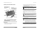
4 For each drive, select the black end of an interface cable not con-
nected to the ATA RAID Controller and plug it into the drive or
drive carrier. The cable’s colored edge denotes Pin 1 and should
be adjacent to the 4-pin power plug.
Note:
Continue to page 22 “Check your installation
and close the case”.