


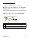


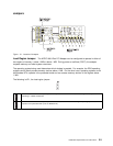
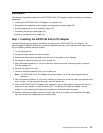

Set Communication Clock Jumpers
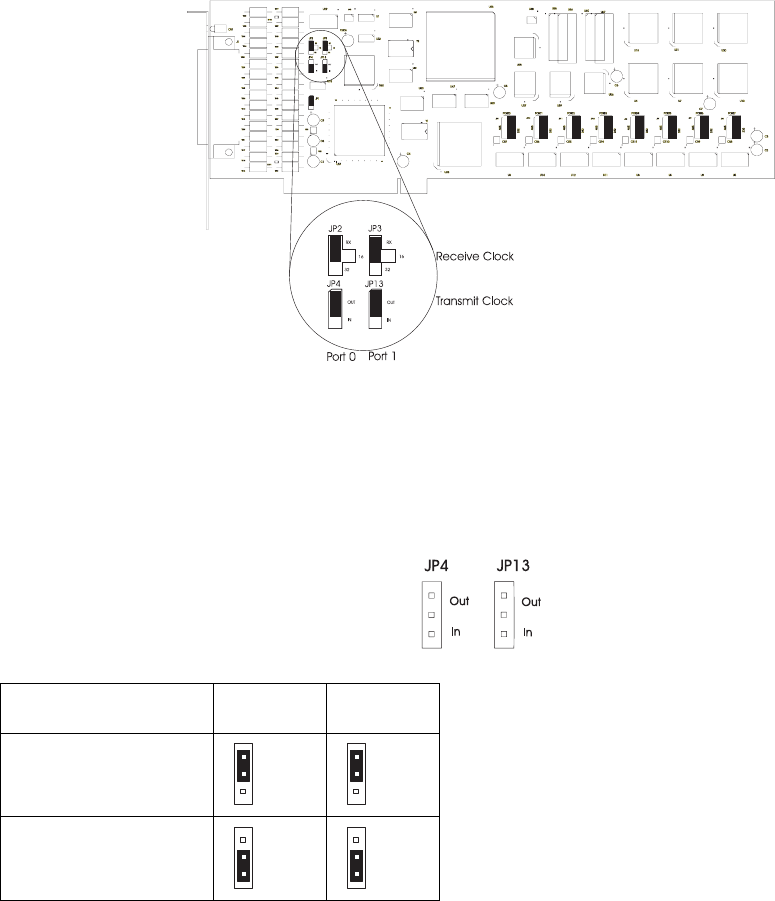
Set the communication-clock jumpers for port 0 (JP2 and JP4) and port 1 (JP3 and JP13) as shown. The
jumper settings are described beginning on page 2-4.
Figure 2-2. Communication Jumper Settings
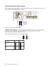
Transmit Clock Jumpers: The transmit-clock jumpers determine whether the transmit clocks for
ports 0 and 1 are an output (the data-terminal equipment provides the clock) or an input (the
data-communications equipment provides the clock).
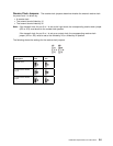
The following shows the settings for transmit clock jumpers.
Description
Port 0
JP4
Port 1
JP13
Output clock to external
device
Input clock from external
device
2-4 ARTIC186 8-Port PCI Adapter GTO