


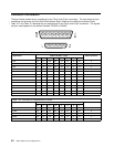
Connector Information
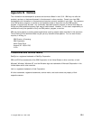
The figure below shows the pin numbering for the 78-pin and 25-pin connectors. The connectors and pin
| numbering are the same for the 8-Port Direct Modem Attach Cable and the Multiport Interface Cable.
| Table 5-2 and Table 5-3 describe the pin assignments for the 78-pin and 25-pin connectors. The signals
and pins used depend on the defined interface, RS-232 or RS-485.
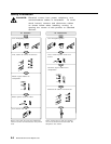
Table 5-2. Connector Pin Assignments for RS-232
Signal Name 78-Pin Connector - Ports 25-Pin Connector
0 1 2 3 4 5 6 7
TXD 40 04 66 69 73 55 76 58 2
RXD 02 64 28 31 54 75 57 78 3
RTS 01 63 27 30 34 16 37 19 4
CTS 61 25 48 51 15 36 18 39 5
DSR 42 06 68 71 72 33 53 14 6
GND 07 08 11 43 67 70 67 70 7
CD 22 45 09 12 74 56 77 59 8
DTR 60 24 47 50 35 17 38 20 20
RI 30 65 29 32 49 52 10 13 22
TX CLK IN 23 46 15
TX CLK OUT 41 05 24
RX CLK IN 62 26 17
HRS 21 44 23
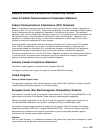
Table 5-3. Connector Pin Assignments for RS-485.
Signal Name 78-Pin Connector - Ports 25-Pin Connector
0 1 2 3 4 5 6 7
TXDA 01 63 27 30 34 16 37 19 4
TXDB 40 04 66 69 73 55 76 58 2
RXDA 61 25 48 51 15 36 18 39 5
RXDB 02 64 28 31 54 75 57 78 3
GND 07 08 11 43 67 70 67 70 7
5-2 ARTIC186 8-Port PCI Adapter GTO