


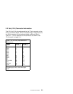
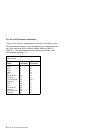
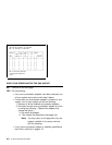

X.21 bis (V.24) Connector Information
The X.21
bis
(V.24) pin assignments for the 37-pin connector on the
PCI co-processor adapter and the corresponding pin assignments for
the 25-pin connector on the optional adapter cable are listed in
Table 3-2. (The pin positions on the connector are shown under
“Pin Numbers” on page 3-1.)
Table 3-2. X.21 bis (V.24) Interface Pin
Assignments
Signal
Name
37-Pin
Connector
25-Pin
Connector
TXD 2 2
RXD 3 3
RTS 4 4
CTS 5 5
DSR 6 6
GND 7 7
CD 8 8
DTR 20 20
RLBT 21 21
RI 22 22
TX CLK IN 24 15
TM 25 25
RX CLK 26 17
LLBT 27 18
Note: Pin 27 can be used as either the
EIA-232 signal, HRS, or the V.24 signal,
LLBT.
Connector Information 3-3