


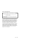

Example 1 — for One Co-Processor Adapter
The following example shows an ICAPARM.PRM file that can be
used if you have one co-processor adapter installed in your system
unit:
# 1 1 1 1 F E1 $
Field Number 1 2 3 4 5 6 7 8 9 1 11
Field
Number Description
1 Beginning-Record Delimiter. If a # is not present, the line
will be treated as a comment.
2 Logical card number of the PCI co-processor adapter.
Range 00–FFh.
3 Shared Memory Address, Meg value.
00 for the IBM ARTIC X.25 Interface Co-Processor PCI
adapter
Range 00–0Fh for all other Intel 186 ARTIC adapters.
(See Field 4).
4 Shared Memory Address, Page Value.
00 for the IBM ARTIC X.25 Interface Co-Processor PCI
adapter
Range 60–6Fh for all other Intel 186 ARTIC adapters.
Used with Meg Value (Field 3) to define the shared
memory window used by the adapter to communicate with
the system unit. The Page Value is the memory offset in
8KB increments. A Meg Value of 00h and a Page Value
of 60h gives a window address of C0000h.
5 Maximum Task Number on the adapter. Range 00–F8h;
set to 10h.
6 Maximum Task Priority. Range 01–FFh; set to 10h.
7 Maximum Task Queue Number. Range 00–FEh; set to
10h.
8 Maximum Task Timer Number. Range 00–FEh; set to
10h.
Special Configuration Information A-3