USER RESPONSIBLE FOR VERIFYING VERSION AND COMPLETENESS
OEM FUNCTIONAL SPECIFICATION ULTRASTAR XP (DFHC) SSA MODELS 1.12/2.25 GB - 1.0" HIGH
4.0 Mechanical
4.1 Small Form Factor Models (CxC)
4.1.1 Weight and Dimensions
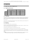
C1C & C2C Models C4C Models
U.S. S.I. Metric U.S. S.I. Metric
Weight 1.00 pounds 0.46 kilograms 1.80 pounds 0.82 kilograms
Height 1.00 inches 25.4 millimeters 1.63 inches 41.3 millimeters
Width 4.00 inches 101.6 millimeters 4.00 inches 101.6 millimeters
Depth 5.75 inches 146.0 millimeters 5.75 inches 146.0 millimeters
4.1.2 Clearances
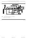
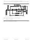
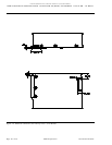
A minimum of 2 mm clearance should be given to the bottom surface except for a 10 mm maximum diam-
eter area around the bottom mounting holes. Figure 11 and Figure 12 show the clearance requirements
(Note 1). For proper cooling it is suggested that a clearance of 6 mm be provided under the drive and on
top of the drive.
There should be 7 mm of clearance between drive's that are mounted with their top sides (see Figure 22 on
page 78 for top view of drive) facing each other.
4.1.3 Mounting
The drive can be mounted with any surface facing down.
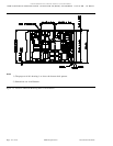
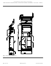
The drive is available with both side and bottom mounting holes. Refer to Figure 11 to Figure 13 for the
location of these mounting holes for each configuration.
The maximum allowable penetration of the mounting screws is 3.8 mm.
The torque applied to the mounting screws must be 0.8 Newton-meters ± 0.1 Newton-meters.
The recommended torque to be applied to the mounting screw is 0.8 Newton-meter ± 0.4 Newton-meter.
IBM will provide technical support to users that wish to investigate higher mounting torques in their appli-
cation.
WARNING: The drive may be sensitive to user mounting implementation due to frame distortion effects.
IBM will provide technical support to assist users to overcome mounting sensitivity.
Source filename=MECHANIC IBM Corporation Page 51 of 87


