USER RESPONSIBLE FOR VERIFYING VERSION AND COMPLETENESS
OEM FUNCTIONAL SPECIFICATION ULTRASTAR XP (DFHC) SSA MODELS 1.12/2.25 GB - 1.0" HIGH
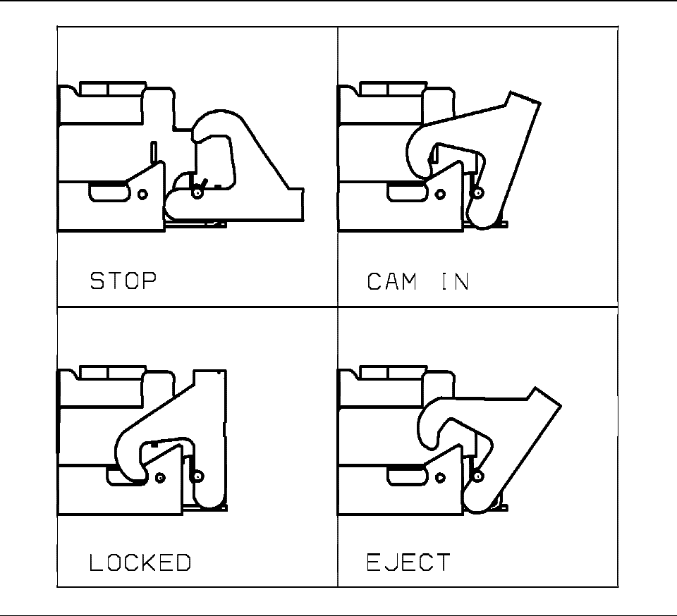
Figure 16. Handle Docking and Ejection System
The handle on the carrier is used for insertion into and extraction from the drawer. It also provides enough
force to ensure seating of the carrier electrical receptacle with the mating connector. Referring to Figure 16,
with the handle in the STOP or open position, a carrier inserted into the auto-docking assembly will have
the connector guide pins inserted into the carrier receptacle but the connector pins will not be making
contact with the carrier receptacle. Moving the carrier handle to the CAM IN position and eventually to the
LOCKED position sets the auto-docking connector with the carrier receptacle and holds the carrier in all the
mounting positions listed above. Moving the handle from the LOCKED position to the EJECT position
provides leverage via the cam surface on the handle acting against the side rails to separate the connector
pins from the receptacle.
Source filename=MECHANIC IBM Corporation Page 59 of 87


