


USER RESPONSIBLE FOR VERIFYING VERSION AND COMPLETENESS
OEM FUNCTIONAL SPECIFICATION ULTRASTAR XP (DFHC) SSA MODELS 1.12/2.25 GB - 1.0" HIGH
The width, period, and tolerance of the negative active Sync pulse is manufacturer dependent, and thus syn-
chronization across different manufacturers or even different product lines of the same manufacturer is not
guaranteed. The Sync pin usage is controlled by mode pages within the mode select command.
This pin is not accessible on CxB model.
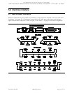
5.5.4 - Write Protect (Option Port Pin 4)
a low active input pin, that when active (pulled below 0.8 V), the drive will prohibit commands that alter the
customer data area portion of the the media from being performed. The state of this pin is monitored on a
per command basis. Refer to "Option pins" section of the Ultrastar XP (DFHC) SSA Models Interface
Specification for a detailed functional description of this pin.
This pin is not accessible on CxB models.
5.5.5 - Ground long (Option Port Pin 5)
The Ground long output pin on CxC and CxB models shall be capable of syncing 1.0 Amp of current. This
pin is longer than any others in the option block to allow for the ground to mate first or last in a hot-plug or
hot-unplug situation.
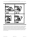
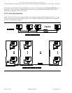
5.5.6 - Device Activity Pin/Indicator (Option Port Pin 6)
A low active LED output pin on CxC models can be used to drive an external Light Emitting Diode. CxB
models have an integrated Green LED. Refer to the "Option Pins" section of the Ultrastar XP (DFHC)
SSA Models Interface Specification for a detailed functional description of this pin/LED.
CxC models provide up to 24 mA of TTL level LED sink current capability. Current limiting for the LED
is provided on the electronics card. The anode may be tied to the + 5V power source (provided on the the
unitized connector). The LED Cathode is then connected to the Device Activity pin to complete the circuit.
5.5.7 + 5V (Option Port Pin 7)
The +5Voutput pin on CxC and CxB models shall supply up to 1.0 Amp of current limited + 5 V (+/-
10%), as long as power is supplied to the device.
5.5.8 - Device Fault Pin/Indicator (Option Port Pin 8)
The Device Fault pin on CxC models can be used to drive an external Light Emitting Diode. CxB models
have an integrated Amber LED. Refer to the "Option Pins" section of the Ultrastar XP (DFHC) SSA
Models Interface Specification for a detailed functional description of this pin/LED.
CxC models provide up to 24 mA of TTL level LED sink current capability. Current limiting for the LED
is provided on the electronics card. The anode may be tied to the + 5V power source (provided on the the
unitized connector). The LED Cathode is then connected to the Device Fault pin to complete the circuit.
Source filename=ELECTRIC IBM Corporation Page 67 of 87