IBM TotalStorage DR550 SMB Version 1.0 ------ 27 May 2005 Page 36
IBM Storage Systems Copyright © 2005 by International Business Machines Corporation
7316-TF3
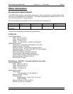
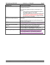
Physical Specifications
Width: 485 mm (19 in)
Depth: 635 mm to 730 mm (29.0 in to 28.74 in)
Height (closed): 43.0 mm (1.7 in)
Height (opened): 410 mm (16.1 in)
Weight: 12.8 kg (28.2 lbs)
LCD Panel
Size: 432 mm (17 in) diagonal, 337.92 (H) x 270.34 mm (V) (13.3 in x 10.6 in)
Type: a-Si TFT active matrix
Pixel pitch: 0.264 mm (H) x 0.264 mm (V)
Operating Environment
Not applicable
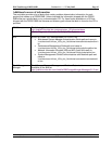
Complementary Products
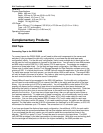
3592 Tape
Connecting Tape to the DR550 SMB
To connect tape to the DR550 SMB, you will need to either add components to the servers and
switches (if you purchased the disk only configuration) or purchase the disk and tape ready
configuration initially. For the disk only configuration, there is one available slot in each server that
can be used for host bus adapters to connect to the tape drives. You will need to have IBM process
an MES order to add p5 520 (9111-520) feature 5716 to each server. The adapter can support a
maximum of three tape drives. For the disk and tape ready configuration, the HBAs are included.
Please note (in either case) that the Tivoli Storage Manager for Data Retention software runs in the
primary p5 520. If a failure should occur, HACMP failover moves the application to the other p5 520.
To insure tape access from both servers, you should add an HBA to each server. The second HBA
will only be used in the event of a failure. Any tasks or jobs involving access to the tape will need to
be rerun once the failover to the other server is completed.
These HBAs will need to be connected to the 2005-H08 switches. For the disk only configuration,
you will need to order additional SFPs to connect the HBA to the switch and the switch to the tape
drives. You can order up to 4 SFPs for each switch. You will need IBM to order feature 2210 (the
quantity will depend on the number of tape drives to be attached) for short wave distances (as
defined by the switch) or feature 2220 for long wave distances (as defined by the switch). Order two
features for the first drive (one to connect the server to the switch and the other to connect the
switch to the first drive. If you have two or three tape drives, then you will need a total of three or
four features respectively. To make each of these connections, you will additionally need to order
the cables. You can order switch feature 5605 (5 meter LC/LC multi-mode cable) for each host
connection. You can then order feature 5625 (25 meter LC/LC multi-mode cable) for each tape
connection if the tape is within 25 meters. If you need something longer, the cable can be customer
supplied. The fiber cable must be 50.0/125 micrometers for distances up to 300 meters, or 62.5/125
micrometers for distances up to 175 meters. The connection is a LC connector type.
If you have purchased the disk and tape ready configuration, the additional 4 SFPs for each switch
are included and the connections between the host bus adapters and switch ports have been done.
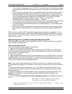
If you purchased the disk only version you will need to make the connections as shown in the
diagram. The SFPs in ports 5, 6, and 7 should be used to connect to the tape drives. The 3592
(with WORM cartridges) is the ideal tape solution for data retention. With write once technology built
into the cartridge and dual ports on the drive (for higher availability), the 3592 provides non-


