


48 PC 300 GL and 300 PL
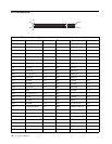
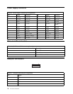
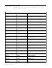
Input/output address map
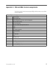
The following lists resource assignments for the I/O address map. Any addresses
that are not shown are reserved.
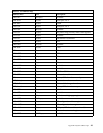
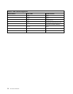
Table 33. I/O address map
Address (hex) Size Description
0000–000F 16 bytes DMA 1
0010–001F 16 bytes General I/O locations - available to PCI bus
0020–0021 2 bytes Interrupt controller 1
0023–003F 30 bytes General I/O locations - available to PCI bus
0040–0043 4 bytes Counter/timer 1
0044–00FF 28 bytes General I/O locations - available to PCI bus
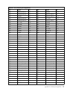
0060 1 byte Keyboard controller byte - reset IRQ
0061 1 byte System port B
0064 1 byte Keyboard controller, CMB/STAT byte
0070, bit 7 1 bit Enable NMI
0070, bits 6:0 1 bit Real-time clock, address
0071 1 byte Real-time clock, data
0072–007F 14 bytes General I/O locations - available to PCI bus
0080 1 byte POST checkpoint register during POST only
008F 1 byte Refresh page register
0080–008F 16 bytes ICH1, DMA page registers
0090–0091 15 bytes General I/O locations - available to PCI bus
0092 1 byte PS/2 keyboard controller registers
0093–009F 15 bytes General I/O locations
00A0–00A1 2 bytes Interrupt controller 2
00A2–00BF 30 bytes APM control
00C0–00DF 31 bytes DMA 2
00E0–00EF 16 bytes General I/O locations - available to PCI bus
00F0 1 byte Coprocessor error register
00F1–016F 127 bytes General I/O locations - available to PCI bus
0170–0177 8 bytes Secondary IDE channel
01F0–01F7 8 bytes Primary IDE channel
0200–0207 8 bytes Available
0220–0227 8 bytes Serial port 3 or 4
0228–0277 80 bytes General I/O locations - available to PCI bus
0278–027F 8 bytes LPT3