


Chapter 2. System board features
Connector panel
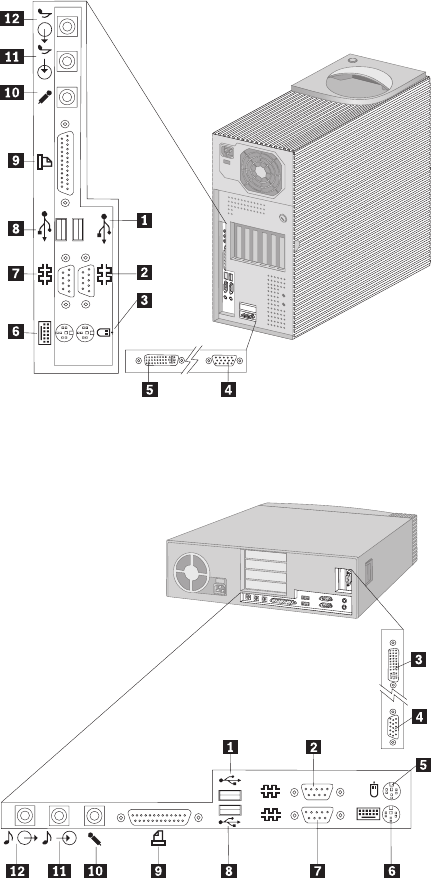
Each connector for a features that is integrated into the system board can be identified by an icon directly
below the connector. A connectors provided by an adapter might not have an identifying icon.
For pin-out details on connectors, see Appendix A, “Connector pin assignments” on page 25.
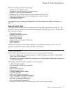
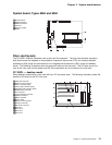
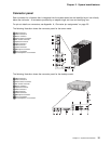
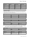
The following illustration shows the connector panel for the tower model:
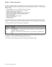
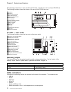
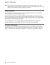
The following illustration shows the connector panel for the desktop model:
1USB connector 2
2Serial connector 2
3Mouse connector
4SVGA monitor connector
5DVI monitor connector
6Keyboard connector
7Serial connector 1
8USB connector 1
9Parallel connector
1Microphone connector
11Line in connector
12Line/headphone out connector
2
2
1
1
1USB connector 2
2Serial connector 2
3SVGA monitor connector
4DVI monitor connector
5Mouse connector
6Keyboard connector
7Serial connector 1
8USB connector 1
9Parallel connector
1Microphone connector
11Line in connector
12Line/headphone out connector
2
2
1
1
Chapter 2. System board features 15