


144
CHAPTER 11 SERIAL INTERFACE CHANNEL 2
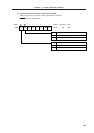
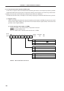
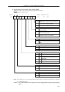
Baud Rate Generator Input Clock SelectionMDL3 MDL2 MDL1 MDL0
0
0
0
0
0
0
0
0
1
1
1
1
1
1
1
1
0
0
0
0
1
1
1
1
0
0
0
0
1
1
1
1
0
0
1
1
0
0
1
1
0
0
1
1
0
0
1
1
0
1
0
1
0
1
0
1
0
1
0
1
0
1
0
1
f
SCK/16
f
SCK/17
f
SCK/18
f
SCK/19
f
SCK/20
f
SCK/21
f
SCK/22
f
SCK/23
f
SCK/24
f
SCK/25
f
SCK/26
f
SCK/27
f
SCK/28
f
SCK/29
f
SCK/30
f
SCK
Note
0
1
2
3
4
5
6
7
8
9
10
11
12
13
14
—
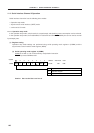
65432107
Symbol
BRGC TPS3 TPS2 TPS1 TPS0 MDL3 MDL2 MDL1 MDL0
FF73H 00H R/W
Address After Reset R/W
k
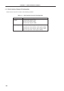
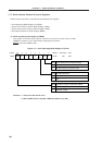
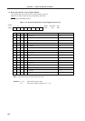
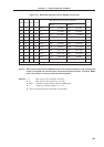
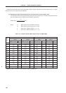
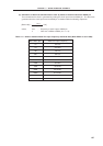
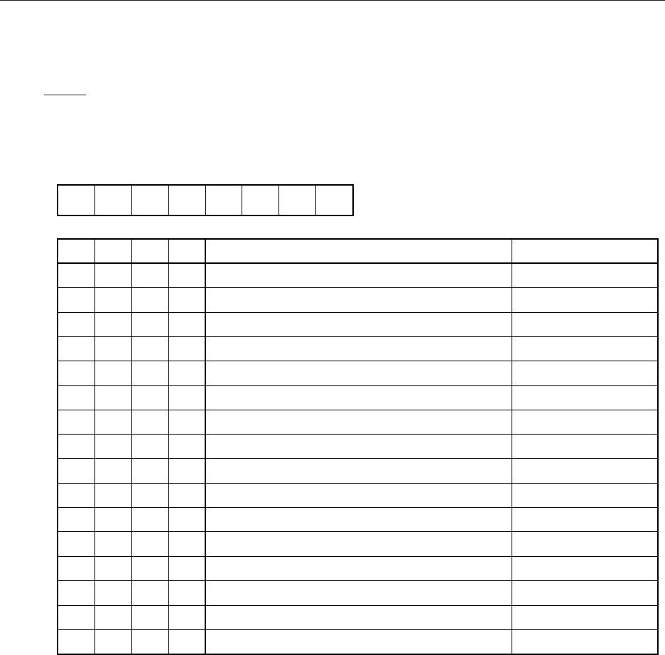
(4) Baud rate generator control register (BRGC)
This register sets the serial clock for serial interface channel 2.
BRGC is set with an 8-bit memory manipulation instruction.
RESET input sets BRGC to 00H.
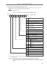
Figure 11-6. Baud Rate Generator Control Register Format (1/2)
Note Can only be used in 3-wire serial I/O mode.
Remarks 1. f
SCK : 5-bit counter source clock
2. k : Value set in MDL0 to MDL3 (0 ≤ k ≤ 14)