


57
CHAPTER 4 PORT FUNCTIONS
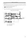
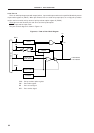
4.2.2 Port 1
Port 1 is an 8-bit input/output port with output latch. It can specify the input mode/output mode in 1-bit units with
a port mode register 1 (PM1). When P10 to P17 pins are used as input ports, an on-chip pull-up resistor can be used
to them in 8-bit units with a pull-up resistor option register L (PUOL).
Dual-functions include an A/D converter analog input.
RESET input sets port 1 to input mode.
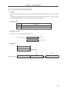
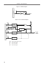
Figure 4-4 shows a block diagram of port 1.
Caution A pull-up resistor cannot be used for pins used as A/D converter analog input.
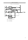
Figure 4-4. P10 to P17 Block Diagram
PUO : Pull-up resistor option register
PM : Port mode register
RD : Port 1 read signal
WR : Port 1 write signal
P-ch
WR
PM
WR
PORT
RD
WR
PUO
V
DD
P10/ANI0
P17/ANI7
Selector
PUO1
Output Latch
(P10 to P17)
PM10-PM17
Internal bus