


198
CHAPTER 13 STANDBY FUNCTION
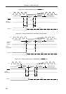
13.2.2 STOP mode
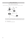
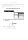
(1) STOP mode set and operating status
The STOP mode is set by executing the STOP instruction.
Cautions 1. When the STOP mode is set, the X2 pin is internally connected to V
DD via a pull-up resistor
to minimize the leakage current at the crystal oscillator. Thus, do not use the STOP mode
in a system where an external clock is used for the main system clock.
2. Because the interrupt request signal is used to clear the standby mode, if there is an
interrupt source with the interrupt request flag set and the interrupt mask flag reset, the
standby mode is immediately cleared if set. Thus, the STOP mode is reset to the HALT
mode immediately after execution of the STOP instruction. After the wait set using the
oscillation stabilization time select register (OSTS), the operating mode is set.
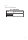
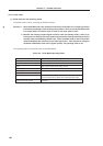
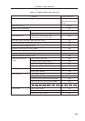
The operating status in the STOP mode is described below.
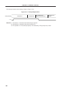
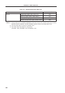
Table 13-3. STOP Mode Operating Status
Item STOP Mode Operating Status
Clock generator Oscillation stops.
CPU Operation stops.
Port Status before STOP mode setting is held.
8-bit timer/event counter 5, 6 Operable when TI5 and TI6 are selected for the count clock.
Watchdog timer Operation stops.
A/D converter
Serial interface Three-wire serial I/O is operable when the externally input
clock is selected as the serial clock. UART operation stops.
External interrupt request Operable.