


8086
MASKABLE INTERRUPT (INTR)
The 8086 provides a single interrupt request input
(INTR) which can be masked internally by software
with the resetting of the interrupt enable FLAG
status bit The interrupt request signal is level trig-
gered It is internally synchronized during each clock
cycle on the high-going edge of CLK To be re-
sponded to INTR must be present (HIGH) during
the clock period preceding the end of the current
instruction or the end of a whole move for a block-
type instruction During the interrupt response se-
quence further interrupts are disabled The enable
bit is reset as part of the response to any interrupt
(INTR NMI software interrupt or single-step) al-
though the FLAGS register which is automatically
pushed onto the stack reflects the state of the proc-
essor prior to the interrupt Until the old FLAGS reg-
ister is restored the enable bit will be zero unless
specifically set by an instruction
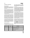
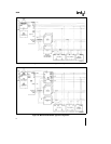
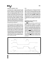
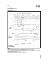
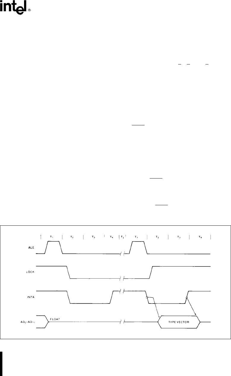
During the response sequence (Figure 6) the proc-
essor executes two successive (back-to-back) inter-
rupt acknowledge cycles The 8086 emits the LOCK
signal from T
2
of the first bus cycle until T
2
of the
second A local bus ‘‘hold’’ request will not be hon-
ored until the end of the second bus cycle In the
second bus cycle a byte is fetched from the external
interrupt system (eg 8259A PIC) which identifies
the source (type) of the interrupt This byte is multi-
plied by four and used as a pointer into the interrupt
vector lookup table An INTR signal left HIGH will be
continually responded to within the limitations of the
enable bit and sample period The INTERRUPT RE-
TURN instruction includes a FLAGS pop which re-
turns the status of the original interrupt enable bit
when it restores the FLAGS
HALT
When a software ‘‘HALT’’ instruction is executed the
processor indicates that it is entering the ‘‘HALT’’
state in one of two ways depending upon which
mode is strapped In minimum mode the processor
issues one ALE with no qualifying bus control sig-
nals In maximum mode the processor issues ap-
propriate HALT status on S
2
S
1
and S
0
and the
8288 bus controller issues one ALE The 8086 will
not leave the ‘‘HALT’’ state when a local bus ‘‘hold’’
is entered while in ‘‘HALT’’ In this case the proces-
sor reissues the HALT indicator An interrupt request
or RESET will force the 8086 out of the ‘‘HALT’’
state
READMODIFYWRITE (SEMAPHORE)
OPERATIONS VIA LOCK
The LOCK
status information is provided by the
processor when directly consecutive bus cycles are
required during the execution of an instruc-
tion This provides the processor with the capability
of performing readmodifywrite operations on
memory (via the Exchange Register With Memory
instruction for example) without the possibility of an-
other system bus master receiving intervening mem-
ory cycles This is useful in multi-processor system
configurations to accomplish ‘‘test and set lock’’ op-
erations The LOCK
signal is activated (forced LOW)
in the clock cycle following the one in which the soft-
ware ‘‘LOCK’’ prefix instruction is decoded by the
EU It is deactivated at the end of the last bus cycle
of the instruction following the ‘‘LOCK’’ prefix in-
struction While LOCK
is active a request on a RQ
GT pin will be recorded and then honored at the end
of the LOCK
231455–9
Figure 6 Interrupt Acknowledge Sequence
11