


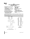

8086
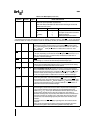
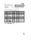
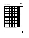
Table 1 Pin Description (Continued)
Symbol Pin No Type Name and Function
S
2
S
1
S
0
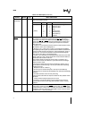
26–28 O These signals float to 3-state OFF in ‘‘hold acknowledge’’ These status
lines are encoded as shown
(Continued)
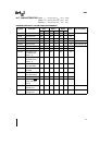
S
2
S
1
S
0
Characteristics
0 (LOW) 0 0 Interrupt Acknowledge
0 0 1 Read IO Port
0 1 0 Write IO Port
0 1 1 Halt
1 (HIGH) 0 0 Code Access
1 0 1 Read Memory
1 1 0 Write Memory
1 1 1 Passive
RQGT
0
30 31 IO REQUESTGRANT pins are used by other local bus masters to force
the processor to release the local bus at the end of the processor’s
RQ
GT
1
current bus cycle Each pin is bidirectional with RQGT
0
having higher
priority than RQ
GT
1
RQGT pins have internal pull-up resistors and
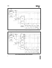
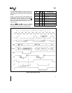
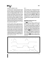
may be left unconnected The requestgrant sequence is as follows
(see Page 2-24)
1 A pulse of 1 CLK wide from another local bus master indicates a local
bus request (‘‘hold’’) to the 8086 (pulse 1)
2 During a T
4
or T
1
clock cycle a pulse 1 CLK wide from the 8086 to
the requesting master (pulse 2) indicates that the 8086 has allowed the
local bus to float and that it will enter the ‘‘hold acknowledge’’ state at
the next CLK The CPU’s bus interface unit is disconnected logically
from the local bus during ‘‘hold acknowledge’’
3 A pulse 1 CLK wide from the requesting master indicates to the 8086
(pulse 3) that the ‘‘hold’’ request is about to end and that the 8086 can
reclaim the local bus at the next CLK
Each master-master exchange of the local bus is a sequence of 3
pulses There must be one dead CLK cycle after each bus exchange
Pulses are active LOW
If the request is made while the CPU is performing a memory cycle it
will release the local bus during T
4
of the cycle when all the following
conditions are met
1 Request occurs on or before T
2
2 Current cycle is not the low byte of a word (on an odd address)
3 Current cycle is not the first acknowledge of an interrupt acknowledge
sequence
4 A locked instruction is not currently executing
If the local bus is idle when the request is made the two possible events
will follow
1 Local bus will be released during the next clock
2 A memory cycle will start within 3 clocks Now the four rules for a
currently active memory cycle apply with condition number 1 already
satisfied
LOCK 29 O LOCK output indicates that other system bus masters are not to gain
control of the system bus while LOCK
is active LOW The LOCK signal
is activated by the ‘‘LOCK’’ prefix instruction and remains active until the
completion of the next instruction This signal is active LOW and floats
to 3-state OFF in ‘‘hold acknowledge’’
4