Software Developer’s Manual 133
Power Management
6.3.1.1 Dr State
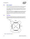
At initial boot-up, once LAN_PWR_GOOD is asserted, the Ethernet controller reads the
EEPROM. If the
APM Mode bit in the EEPROM’s Initialization Control Word 2 is set then APM
Wakeup is enabled.
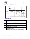
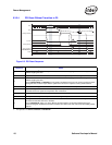
The system may maintain RST# asserted for an arbitrary time. During this time, and for up to 1 ms
afterwards, the Ethernet controller does not assert any PCI signals except PME#.
During operation, the system may assert RST# at any time. In particular, if the system wishes an
Ethernet controller to enter the D3cold state it must assert RST# before dropping main power. Any
time RST# is asserted, the Ethernet controller transitions to the Dr state. It also floats all PCI
signals except PME# and remains in the “reset” state until no more than 1 ms after the deassertion
of RST#.
Internally, the Ethernet controller treats the reset state equivalently to D3. Any Wakeups enabled
before entering reset is maintained. For power savings, the Ethernet controller shuts down some
internal clocks and registers and deasserts PWR_STATE1. If Wakeup is not enabled, the Ethernet
controller also deasserts PWR_STATE0. As a result, the Ethernet controller won’t transmit any
frames in Dr state or send idles in TBI mode (
82544GC/EI)/internal SerDes (82546GB/EB and
82545GM/EM)
1
.
The deassertion (rising edge) of RST# causes a transition to D0u.
6.3.1.2 D0u State
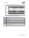
The D0u state is a low-power state used after RST# is deasserted, or when coming out of D3, but
before the Ethernet controller is initialized.
When entering D0u, the Ethernet controller disables Wakeups, resets the PHY, and then re-reads
the EEPROM. If the
APM Mode bit in the EEPROM’s Initialization Control Word 2 is set, then
APM Wakeup is enabled.
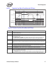
Internally, D0u is treated like D3 and some internal clocks and registers are shut down. The D0u
state is exited when the system enables memory space access to the Ethernet controller by writing a
1b to the
Memory Access Enable bit of the PCI Command Register.
Note: In order for hardware to transition from D3 to the D0 state properly, BIOS should not alter the
Memory Access Enable or the I/O Access Enable bit of the PCI Command Register. Also, the PCI
configuration space must be programmed when hardware transitions out of D3 to D0.
1. Not applicable to the 82541xx, 82547GI/EI, or 82540EP/EM.


