


12
•
Installation
2.6 Connector Pin Assignments
2.6.1 PCI-7200 Pin Assignments
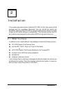
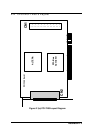
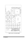
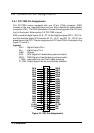
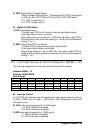
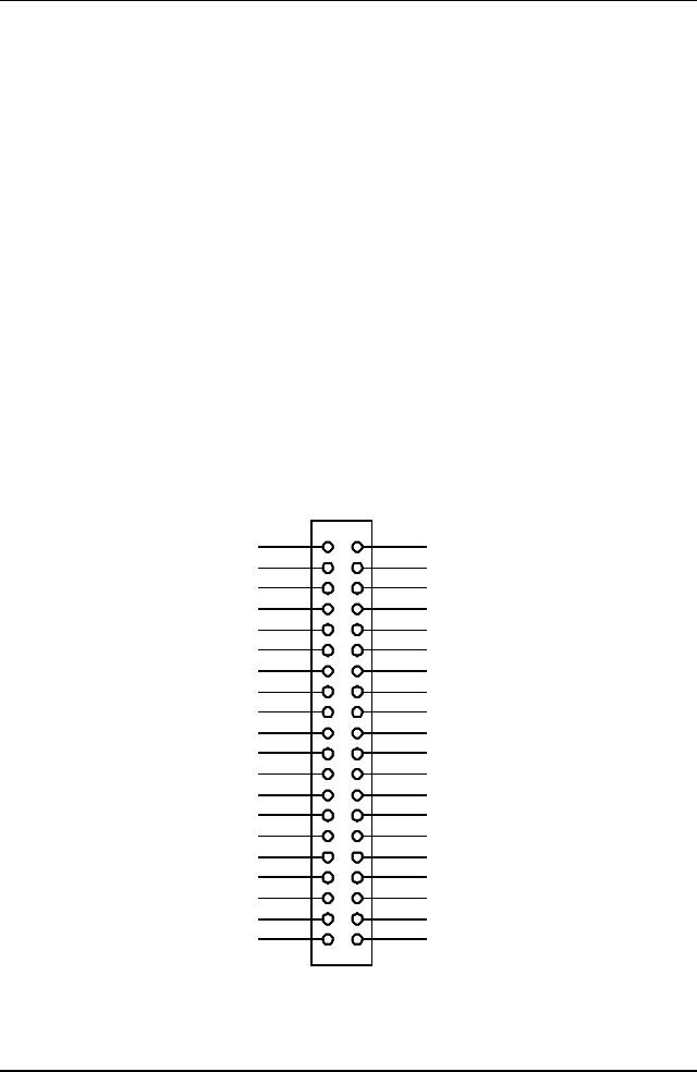
The PCI-7200 comes equipped with one 37-pin D-Sub connector (CN2)
located on the rear mounting plate and one 40-pin female flat cable header
connector (CN1). The CN2 is located on the rear mounting plate; the CN1 is on
front of the board. Refer section 2.2 PCI-7200‘s layout.
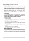
CN2 is used for digital inputs (DI 0 ~ DI 15) and digital outputs (DO 0 ~ DO 15),
and the reminder digital I/O channels DI 16 ~ DI 31 and DO 16 ~ DO 31 are
presented on the CN1. The pin assignment of CN1 and CN2 is illustrated in the
figure 2.2 and 2.3.
Legend:
DO n : Digital Output CH n
DI n : Digital Input CH n
GND : Ground
ACK : ACK Signal of handshaking communication
REQ : REQ Signal of handshaking communication
I_TRG: Input signal to start the DI data sampling
O_TRG: Output signal can be controlled by software
21
20
2
3 4
5 6
7 8
9 10
11 12
13 14
15 16
17
19
22
23 24
25 26
27 28
37
18
29
35
3433
32
30
31
36
1
39 40
38
DI27
DI28
DI29
DI30
DI31
+5V
O_ACK
O_REQ
DI16
DI17
DI18
DI19
DI20
DI21
DI22
DI23
DI24
DI25
DI26
N/C
N/C
N/C
DO16
DO17
DO18
DO19
DO20
DO21
DO22
DO23
DO24
DO25
DO26
DO27
DO28
DO29
DO30
DO31
GND
O_TR1
21
20
2
3 4
5 6
7 8
9 10
11 12
13 14
15 16
17
19
22
23 24
25 26
27 28
37
18
29
35
3433
32
30
31
36
1
39 40
38
21
20
3
5 6
7 8
9 10
11 12
13 14
15 16
17
19
22
23 24
25 26
27 28
37
18
29
35
3433
32
30
31
36
1
39
38
DI27
DI28
DI29
DI30
DI31
+5V
O_ACK
O_REQ
DI16
DI17
DI18
DI19
DI20
DI21
DI22
DI23
DI24
DI25
DI26
N/C
N/C
N/C
DO16
DO17
DO18
DO19
DO20
DO21
DO22
DO23
DO24
DO25
DO26
DO27
DO28
DO29
DO30
DO31
GND
O_TR1
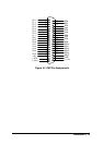
Figure 2.2 CN1 Pin Assignments