


18
•
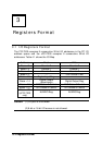
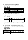
Registers Format
u Digital Input Mode Setting:
I_ACK: Input ACK Enable
1: Input ACK is enabled (input ACK will be asserted after input data is
read by CPU or written to input FIFO)
0: Input ACK is disabled
I_REQ: Input REQ Strobe Enabled
1: Use I_REQ edge to latch input data
0: I_REQ is disabled
I_TIME0: Input Timer 0 Enable
1: Input is sampled by falling edge of Counter 0 output (COUT0)
0: Input Timer 0 is disabled
I_FIFO: Input FIFO Enable Mode
1: Input FIFO is enabled (input data is saved to input FIFO)
0: Input FIFO is disabled
TRGPOL: Input Trigger Polarity
1: I_TRG is Rising Edge Active
0: I_TRG is Falling Edge Active
I_TRG: External Trigger Enable
1: Wait until I_TRG signal is active, digital input sampling will begin
after a rising or falling edge of I_TRG is coming.
0: Start input sampling immediately (if input control register is set)
DIN_EN: Digital Input Enable
1: Digital Input Enable
0: Digital Input Disabled, when this bit is set as 0, all digital input
operation will be stopped.
u Digital Output Mode Setting:
O_ACK: Output ACK Enable
1: Output ACK is enabled, the output circuit will wait for O_ACK after
O_REQ strobe is asserted.
0: Output ACK is disabled
O_REQ: Output REQ Enable
1: Output REQ is enabled, an O_REQ strobe will be generated after
output data is ready
0: Output REQ is disabled
O_TIME1: Output Timer 1 Enable
1: Output Timer 1 is enabled, output data is moved from output FIFO
to DO registers when output of Counter1 goes low.
0: Output Counter 1 is disabled
O_FIFO: Output FIFO Enable
1: Output FIFO is enabled (output data is moved from output FIFO)
0: Output FIFO is disabled