


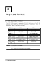
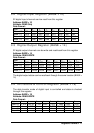

Registers Format
•
21
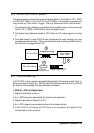
T1_T2: Timer 1 is cascaded with timer 2
1: Timer 1 and timer 2 are cascaded together, output of timer 2
connects to the clock input of timer 1.
0: Not cascaded, the 4 MHz clock is connected to the timer 1 clock
input.
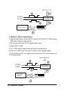
u I_REQ Polarity Selection:
When the input sampling is controlled by the I_REQ signal only, the I_REQ can
be programmed to be rising edge active or falling edge active.
REQ_NEG: I_REQ trigger polarity
1: latch input data on falling edge of I_REQ
0: latch input data on rising edge of I_REQ
u FIFO Control and Status (cPCI-7200 only):
The cPCI-7200 has an extra 2K samples digital input FIFO. The FIFO can be
cleared and monitored by the following bits:
FIFORST (Write only): Clear the on-board DI FIFO
1: Write 1 to clear the data of the FIFO.
0: No operation.
FIFOEF (Read only): Empty flag of the DI FIFO
1: DI FIFO is empty.
0: DI FIFO is not empty.
FIFOFF (Read only): Full flag of the DI FIFO
1: DI FIFO is full.
0: DI FIFO is not full.
Note: The cPCI-7200 has 2 cascaded DI FIFOs. One is located in the PCI
controller chip, the other one is on the PCI-7200 board. The above
bits only control the on-board FIFO. In order to control the on-chip
FIFO, please refer to the AMCC-5933 data book.