


Intel Desktop Board D101GGC Product Guide
16
OM1820
8
AB
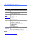
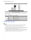
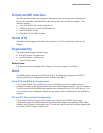
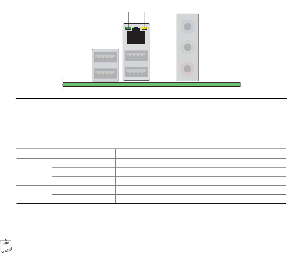
Figure 2. LAN Connector LEDs
Table 4 describes the LED states when the board is powered up and the 10/100 Ethernet LAN
subsystem is operating.
Table 4. RJ-45 10/100 Ethernet LAN Connector LEDs
LED LED State Indicates
Off LAN link is not established A (Green)
On LAN link is established
Blinking LAN activity is occurring
Off 10 Mbits/s data rate is selected B (Yellow)
On (steady state) 100 Mbits/s data rate is selected
Hi-Speed USB 2.0 Support
NOTE
Computer systems that have an unshielded cable attached to a USB port might not meet FCC
Class B requirements, even if no device or a low-speed USB device is attached to the cable.
Use a shielded cable that meets the requirements for a full-speed USB device.
The desktop board supports up to eight USB 2.0; four ports routed to the back panel and four routed
to two internal USB 2.0 headers. USB 2.0 ports are backward compatible with USB 1.1 devices.
USB 1.1 devices will function normally at USB 1.1 speeds.
USB 2.0 support requires both an operating system and drivers that fully support USB 2.0 transfer
rates. Disabling Hi-Speed USB in the BIOS reverts all USB 2.0 ports to USB 1.1 operation. This
may be required to accommodate operating systems that do not support USB 2.0.