


Intel Desktop Board D101GGC Product Guide
vi
Installing and Removing Memory..........................................................................................31
Installing DIMMs...........................................................................................................31
Removing DIMMs.........................................................................................................33
Installing and Removing a PCI Express* x16 Card............................................................... 34
Installing a PCI Express x16 Card ............................................................................... 34
Removing the PCI Express x16 Card ..........................................................................34
Connecting the IDE Cable.....................................................................................................35
Connecting the Serial ATA (SATA) Cable.............................................................................36
Connecting Internal Headers ................................................................................................37
Installing a Front Panel Audio Solution for Intel
®
High Definition Audio.......................38
Connecting Hi-Speed USB 2.0 Headers......................................................................39
Connecting the Front Panel Header............................................................................. 39
Setting Up the Flexible 6-Channel Audio with Jack Re-tasking (Optional) ...........................40
Connecting Fan and Power Cables ......................................................................................41
Connecting Fan Cables................................................................................................41
Connecting Power Cables............................................................................................42
Other Connectors..................................................................................................................43
Setting the BIOS Configuration Jumper................................................................................44
Clearing Passwords ..............................................................................................................45
A Regulatory Compliance
Safety Regulations................................................................................................................51
Place Battery Marking..................................................................................................51
European Union Declaration of Conformity Statement .........................................................52
Product Ecology Statements.................................................................................................53
Lead Free Desktop Board............................................................................................55
EMC Regulations ..................................................................................................................55
Ensure System EMC Compliance................................................................................56
Product Certifications............................................................................................................57
Board-Level Certification Markings ..............................................................................57
Chassis and Component Certifications........................................................................58
Figures
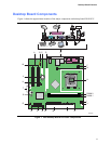
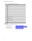
1. Intel Desktop Board D101GGC Components.................................................................11
2. LAN Connector LEDs .....................................................................................................16
3. Location of the Standby Power Indicator........................................................................20
4. Installing the I/O Shield...................................................................................................25
5. Desktop Board D101GGC Mounting Screw Hole Locations ..........................................26
6. Lift Socket Lever.............................................................................................................27
7. Lift the Load Plate and Don’t Touch the Socket Contacts..............................................27
8. Remove the Protective Socket Cover.............................................................................28
9. Remove the Processor from the Protective Processor Cover/Do Not Touch.................28
10. Install Processor.............................................................................................................29
11. Close the Load Plate ......................................................................................................29
12. Connecting the Processor Fan Heat Sink Cable to the Processor Fan Connector........30
13. Use DDR DIMMs............................................................................................................31
14. Installing a DIMM............................................................................................................32
15. Removing a PCI Express x16 Card................................................................................34
16. Connecting the IDE Cable..............................................................................................35
17. Connecting the Serial ATA Cable...................................................................................36