


Installing and Replacing Desktop Board Components
39
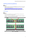
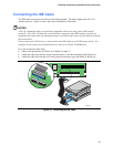
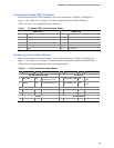
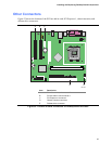
Connecting Hi-Speed USB 2.0 Headers
Before connecting the USB 2.0 headers, observe the precautions in "Before You Begin" on
page 23. See Figure 18, A on page 37 for the location of the black USB 2.0 headers.
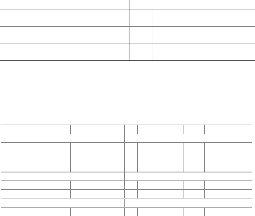
Table 7 shows the pin assignments for the headers.
Table 7. Hi-Speed USB 2.0 Header Signal Names
USB Port A USB Port B
Pin Signal name Pin Signal name
1 Power 2 Power
3 D- 4 D-
5 D+ 6 D+
7 Ground 8 Ground
9 Key 10 No connect
Note: USB ports may be assigned as needed.
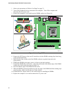
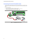
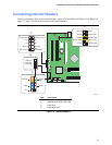
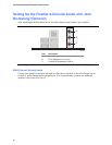
Connecting the Front Panel Header
Before connecting the front panel header, observe the precautions in "Before You Begin" on
page 23. See Figure 18, C on page 37 for the location of the multi-colored front panel header.
Table 8 shows the pin assignments for the front panel header.
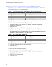
Table 8. Front Panel Header Signal Names
Pin Signal In/Out Description Pin Signal In/Out Description
Hard Drive Activity LED Power LED
1 HD_PWR Out
Hard disk LED pull-
up (330 Ω) to +5 V
2 HDR_BLNK_GRN Out
Front panel green
LED
3 HDA# Out Hard disk active LED 4 HDR_BLNK_YEL Out
Front panel yellow
LED
Reset Switch On/Off Switch
5 Ground Ground 6 SWITCH_ON# In Power switch
7 FP_RESET# In Reset switch 8 Ground Ground
Power Not Connected
9 +5 V Power 10 N/C No pin