


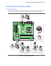
Installing and Replacing Desktop Board Components
37
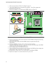
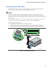
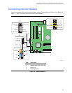
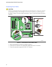
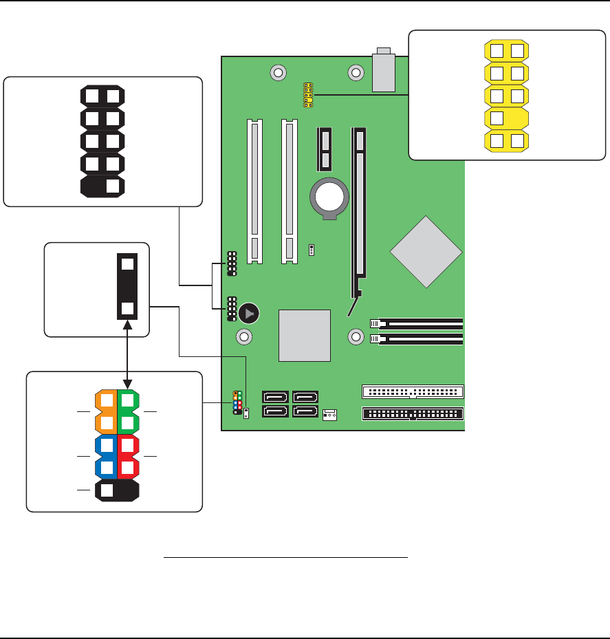
Connecting Internal Headers
Before connecting cables to the internal headers, observe the precautions in "Before You Begin" on
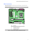
page 23. Figure 18 shows the location of the internal headers.
OM18217
A
C
+5 V
Reset
HD LED
–
On/Off
Power
LED
+
+
–
9
87
65
4
2
3
1
B
Alternate
Front Panel
Power LED
10
87
65
4
2
1
3
No
Connection
Ground
D+
D–
Power (+5 V)
Key (no pin)
Ground
D+
Power (+5 V)
D–
3
+
–
1
D
109
7
65
4
2
1
3
Sense2_Ret
Key (no pin)
Sense1_Ret
Presence#
GND
Port2L
Sense_Send
Port2R
Port1R
Port1L
Item Description
A Hi-speed USB 2.0 (two)
B Alternate front panel power LED
C Front panel
D Front panel audio
Figure 18. Internal Headers