


Contents
v
B Regulatory Compliance
Safety Regulations ............................................................................................................. 79
EMC Regulations ............................................................................................................... 79
Product Certification Markings............................................................................................ 80
Installation Precautions ...................................................................................................... 81
Installation Instructions.......................................................................................................81
Ensure Electromagnetic Compatibility (EMC) Compliance......................................... 81
Chassis and Component Certifications...................................................................... 82
Prevent Power Supply Overload................................................................................ 82
Place Battery Marking................................................................................................ 82
Use Only for Intended Applications............................................................................ 83
Figures
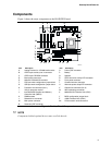
1. Desktop Board Components.......................................................................................... 9
2. Location of the Standby Power Indicator...................................................................... 18
3. DIMM Socket Locations............................................................................................... 23
4. Installing the I/O Shield................................................................................................ 24
5. Location of the Mounting Screw Holes......................................................................... 25
6. Installing the Processor in the Processor Socket ......................................................... 26
7. Attaching the Heatsink to the Processor ...................................................................... 27
8. Attaching the Fan Heatsink Clips to the Processor Socket........................................... 27
9. Connecting the Processor Fan Cable to the Processor Fan Connector ....................... 28
10. Attaching the Fan Heatsink Over the Processor .......................................................... 29
11. Placing the Plastic Clip on the Fan Heatsink................................................................ 29
12. Lowering the Plastic Clip Handle.................................................................................. 30
13. Attaching the Fan to the Fan Heatsink......................................................................... 31
14. Connecting the Processor Fan Cable to the Processor Fan Connector ....................... 31
15. Removing the Fan Heatsink......................................................................................... 32
16. Connecting the IDE Cable............................................................................................ 33
17. BIOS Configuration Jumper Block Location ................................................................. 34
18. PS/2 Port and USB Port Wake Configuration Jumper Block Locations........................ 35
19. Removing the Battery from the Board.......................................................................... 39
20. Back Panel Connectors................................................................................................ 68
21. Audio Connectors ........................................................................................................ 69
22. Power and Hardware Control Connectors.................................................................... 70
23. Add-in Board and Peripheral Interface Connectors...................................................... 71
24. Front Panel Connectors............................................................................................... 72
Tables
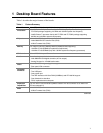
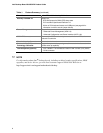
1. Feature Summary .......................................................................................................... 7
2. Supported Processors ................................................................................................. 10
3. Processor and Memory Module Combinations............................................................. 12
4. RJ-45 LAN Connector LEDs ........................................................................................ 16
5. Standby Current Requirements.................................................................................... 19
6. Jumper Settings for the BIOS Setup Program Modes.................................................. 34
7. Jumper Settings for the PS/2 Ports.............................................................................. 35
8. Jumper Settings for the USB Ports .............................................................................. 36
9. BIOS Setup Program Menu Bar................................................................................... 45