Desktop Board Features
19
Power Connectors
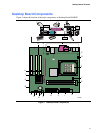
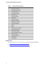
The desktop board has two power connectors. See Figure 11 on page 36 for the location of the
power connectors.
Fan Headers
The desktop board has two chassis fan headers and one processor fan header. See Figure 11 on
page 36 for the location of the fan headers.
Chassis Intrusion
The board supports a chassis security feature that detects if the chassis cover has been removed.
The security feature uses a mechanical switch (not included) on the chassis that can be connected
to the chassis intrusion header on the desktop board. See Figure 11 on page 36 for the location of
the chassis intrusion header.
Suspend to RAM (Instantly Available PC Technology)
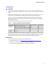
CAUTION
For Instantly Available PC technology, the 5 V standby line for the power supply must be capable
of delivering adequate +5 V standby current. Failure to provide adequate standby current when
using this feature can damage the power supply and/or effect ACPI S3 sleep state functionality.
Instantly Available PC technology enables the board to enter the ACPI S3 (Suspend-to-RAM)
sleep state. While in the S3 sleep state, the computer will appear to be off. When signaled by a
wake-up device or event, the system quickly returns to its last known awake state.
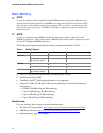
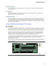
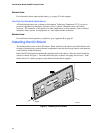
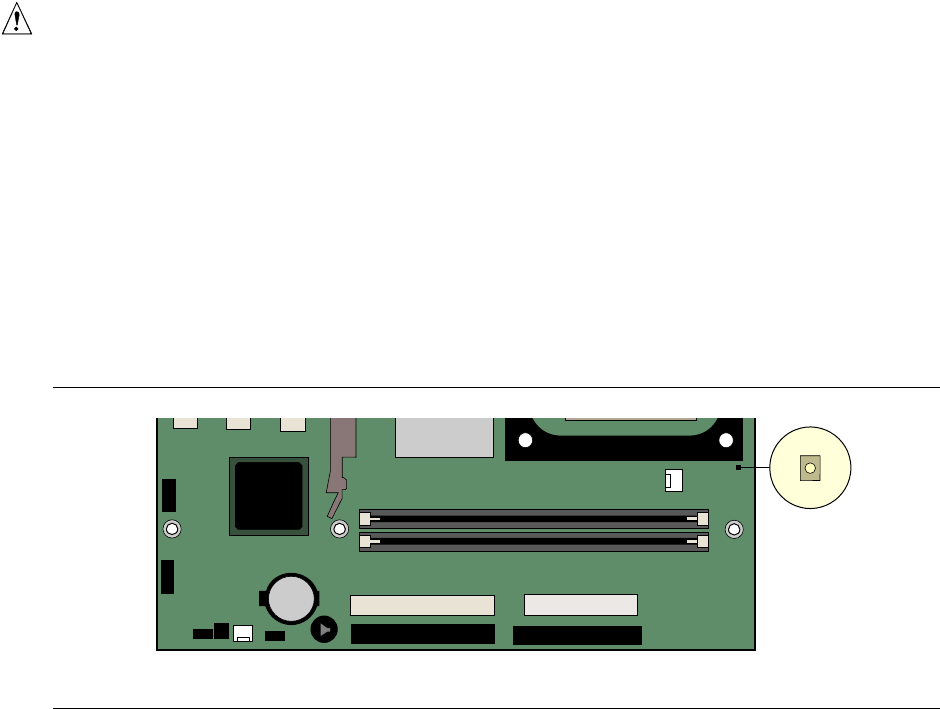
The desktop board’s standby power indicator, shown in Figure 2, is lit when there is standby power
to the system. This includes the memory modules and PCI bus connectors, even when the
computer appears to be off.
If the system has a dual-colored power LED on the front panel, the sleep state is indicated by the
LED turning amber.
OM16287
Figure 2. Location of Standby Power Indicator


