


Contents
vii
B Regulatory Compliance
Safety Regulations ..............................................................................................................83
European Union Declaration of Conformity Statement ........................................................83
Product Ecology Statements ...............................................................................................84
EMC Regulations ................................................................................................................85
Product Certification Markings (Board Level) ......................................................................86
Figures
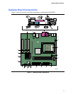
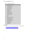
1. Desktop Board Components.........................................................................................11
2. Location of Standby Power Indicator.............................................................................19
3. Installing the I/O Shield.................................................................................................24
4. Desktop Board Mounting Screw Holes..........................................................................25
5. Installing a Processor....................................................................................................26
6. Connecting the Processor Fan Heatsink Cable to the Processor Fan Header ..............27
7. Installing Memory..........................................................................................................28
8. Removing the AGP Card ..............................................................................................30
9. Connecting the IDE Cable.............................................................................................32
10. Internal Headers ...........................................................................................................33
11. Location of Hardware Control and Power Connectors ..................................................36
12. Add-in Card and Peripheral Interface Connectors.........................................................38
13. Location of the BIOS Configuration Jumper Block ........................................................39
14. Back Panel Connectors ................................................................................................41
15. Removing the Battery from the Desktop Board.............................................................46