


ECB-870
ECB-870 User’s Manual 35
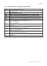
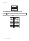
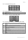
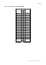
3.10.12 Fast & Standard IrDA Connector (JIR)
Signal PIN PIN Signal
+5V 1 6 NC
NC 2 7 CIRRX
IRRX 3 8 5V Standby
GND 4 9 NC
IRTX 5 10 NC
3.10.13 Signal Configuration – Fast & Standard IrDA Connector (JIR)
IRRX Infrared Receiver input
IRTX Infrared Transmitter output
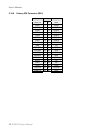
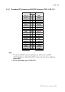
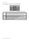
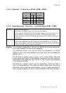
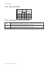
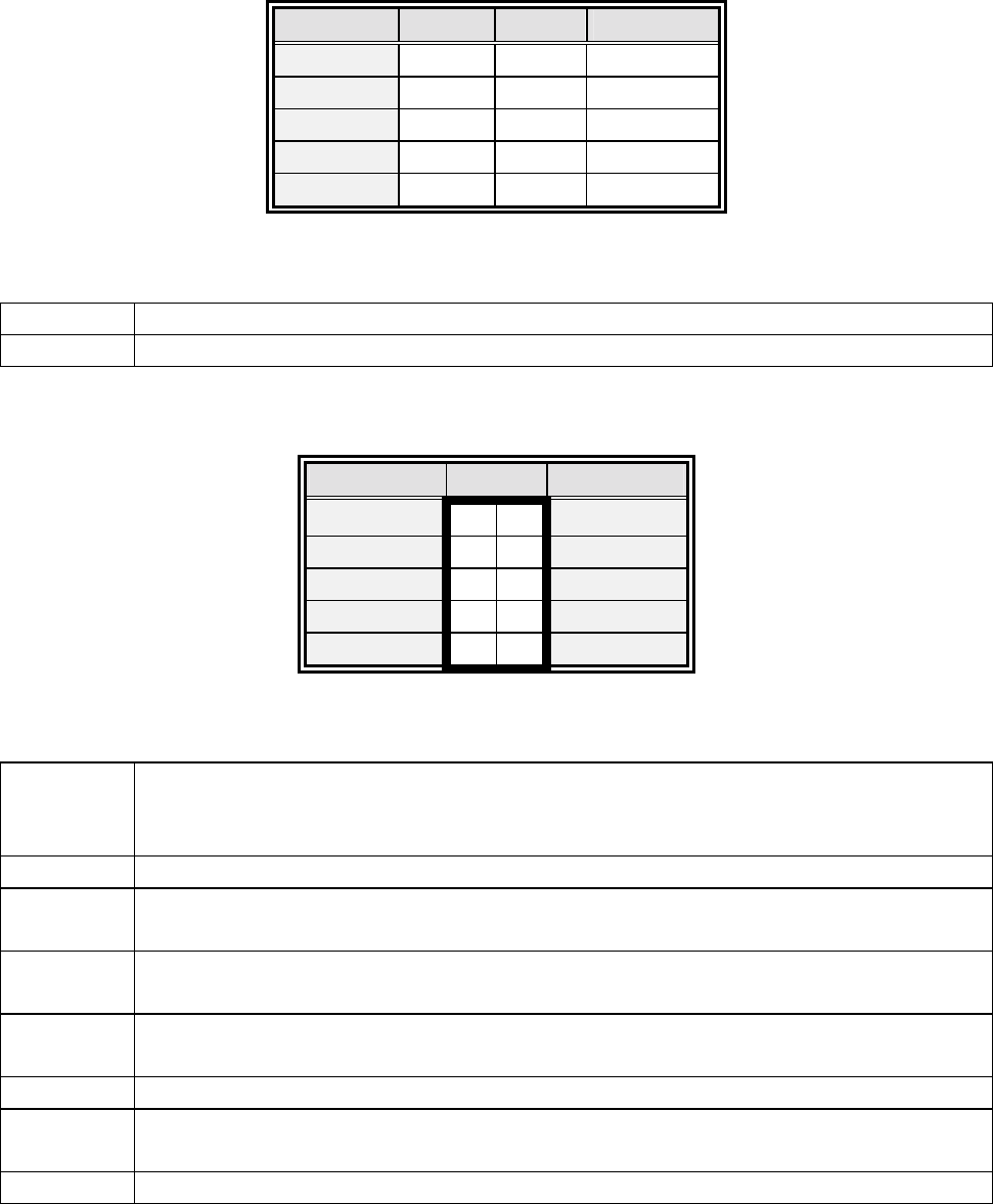
3.10.14 Serial Port 1 / 2 Connector in RS-232 (JCOM1, JCOM2)
Signal PIN Signal
DCD 1 2 RxD
TxD 3 4 DTR
GND 5 6 DSR
RTS 7 8 CTS
RI 9 10 NC
3.10.15 Signal Description – Serial Port 1 / 2 in RS-232 Mode (JCOM1, JCOM2)
TxD Serial output. This signal sends serial data to the communication link. The signal is set to a
marking state on hardware reset when the transmitter is empty or when loop mode operation
is initiated.
RxD Serial input. This signal receives serial data from the communication link.
DTR Data Terminal Ready. This signal indicates to the modem or data set that the on-board UART
is ready to establish a communication link.
DSR Data Set Ready. This signal indicates that the modem or data set is ready to establish a
communication link.
RTS Request To Send. This signal indicates to the modem or data set that the on-board UART is
ready to exchange data.
CTS Clear To Send. This signal indicates that the modem or data set is ready to exchange data.
DCD Data Carrier Detect. This signal indicates that the modem or data set has detected the data
carrier.
RI Ring Indicator. This signal indicates that the modem has received a telephone ringing signal.