


Intel
®
Q965 Express Chipset
October 2007 DM
315664-002US 4
—Intel Q965 Express Chipset
4.6.1 Installation of a new Operating System ..................................................... 45
4.6.2 Drivers Installation................................................................................. 45
5.0 Error Messages and Beep Codes .............................................................................. 46
5.1 Speaker ........................................................................................................... 46
5.2 BIOS Beep Codes .............................................................................................. 46
5.3 BIOS Error Messages ......................................................................................... 46
5.4 Port 80h POST Codes......................................................................................... 47
Figures
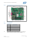
1 Dev Kit Board Main Components, Headers and Jumper Locations.................................... 14
2 Rear Panel I/O Connectors ........................................................................................ 17
3 BTX Type I Thermal Module Assembly (TMA) ............................................................... 25
4 Menu Bar................................................................................................................ 26
5 Development Kit Board ............................................................................................. 32
6 Align the Development Kit Board and SRM................................................................... 34
7 Assembled SRM and board ........................................................................................ 35
8 Align the heatsink with holes on the SRM and board ..................................................... 36
9 Tighten the heatsink on the SRM and board................................................................. 37
10 Secure the front side of the heatsink to the SRM .......................................................... 38
11 Secure the read end of heatsink to the SRM ................................................................ 39
12 Memory Channel and DIMM Configuration ................................................................... 40
13 Dual Channel (Interleaved) Mode Configuration with two DIMMs .................................... 41
14 Dual Channel (Interleaved) Mode Configuration with three DIMMs .................................. 41
15 Dual Channel (Interleaved) Mode Configuration with four DIMMs .................................... 42
16 Single Channel (Asymmetric) Mode Configuration with one DIMM ...................................42
17 Single Channel (Asymmetric) Mode Configuration with 3x DIMMs ................................... 43
18 Back Panel Audio Connector Options for Eight-channel Audio Subsystem ......................... 43
19 LAN Connector LED locations ..................................................................................... 45
Tables
1 Glossary of Terms and Acronyms .................................................................................9
2 Intel Literature Centers............................................................................................. 11
3 Development Kit Features Summary........................................................................... 12
4 Core Components .................................................................................................... 14
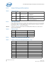
5 Jumper Settings.......................................................................................................15
6 LED Description ....................................................................................................... 15
7 Header and Connector Descriptions ............................................................................ 15
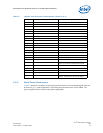
8 Back panel connectors .............................................................................................. 17
9 Intel® SDVO to PCI Express* connector mapping for MEC cards..................................... 18
10 PCI Express* (x1) Pinout .......................................................................................... 20
11 Front Panel Jumper Setting ....................................................................................... 21
12 Front Panel USB Header............................................................................................ 21
13 Front Audio Header .................................................................................................. 22
14 High Definition Audio Header ..................................................................................... 22
15 2x12 BTX Power Connector .......................................................................................23
16 2x2 Auxiliary 12V Power Connector ............................................................................ 23
17 SATA Pinout ............................................................................................................ 24
18 Fan connectors ........................................................................................................ 24
19 BIOS Setup Program Menu Bar .................................................................................. 27
20 BIOS Setup Program Function Keys ............................................................................ 27
21 Back panel task (Audio) ............................................................................................44
22 LAN Connector LED status......................................................................................... 45