


Intel Q965 Express Chipset—Setting Up & Configuring the Development Kit
Intel
®
Q965 Express Chipset
DM October 2007
45 Order Number: 315664-002US
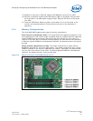
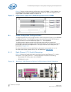
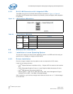
4.5.2 RJ-45 LAN Connector with Integrated LEDs
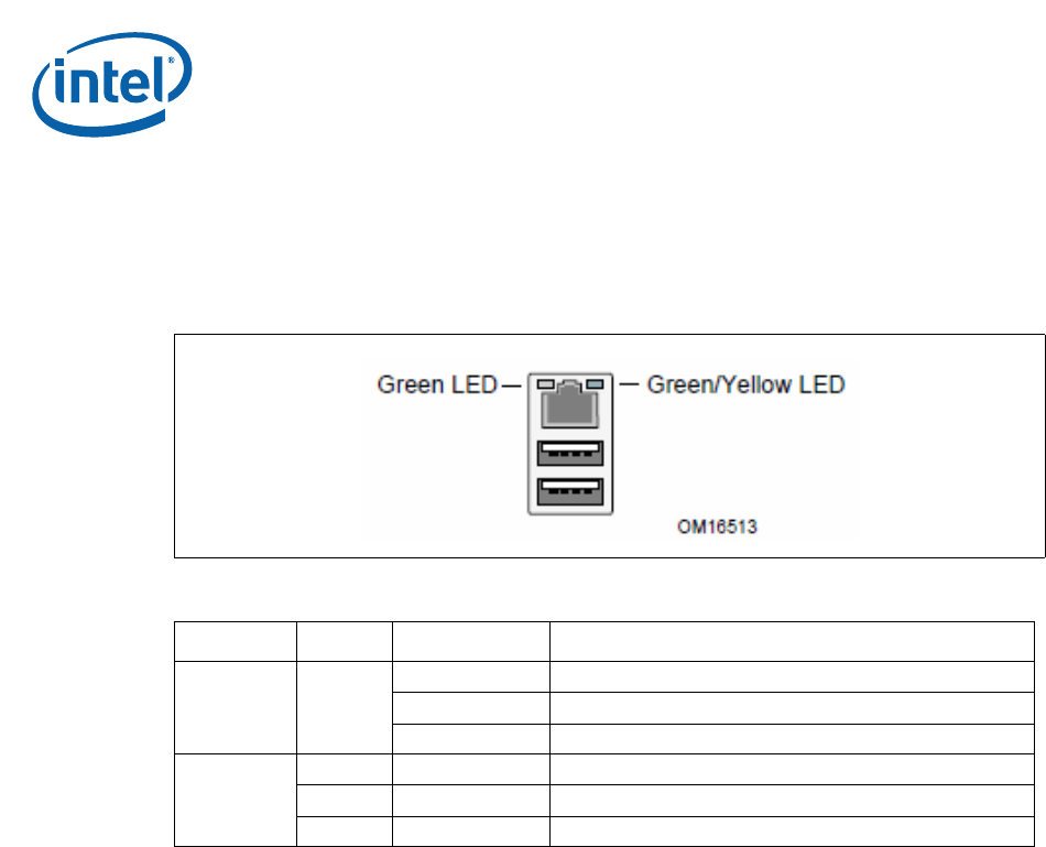
Two LEDs are built into the RJ-45 LAN connector as shown in Figure 19. Table 22
describes the LED states when the board is powered up and the Gigabit LAN subsystem
is operating.
4.6 Software Kit Installation
4.6.1 Installation of a new Operating System
The user will required to install a new operating system on a SATA hard disk using an
optical drive or loading an image to the hard disk.
4.6.2 Drivers Installation
Once the image is loaded onto the platform and the clean build of OS is done,
Install all the relevant drivers:
•Intel
®
Chipset Software Installation Utility – Chipset INF files needs to be installed
first
•Intel
®
Embedded Graphics Drivers or Intel
®
Graphics Media Accelerator Drivers
•Intel
®
PRO Network Connections LAN Driver
• Others optional – HECI driver, AMT Serial Over LAN, Intel
®
Management Engine
Interface Driver (QST), Intel Matrix Storage Manager
After installation, go to device manager and make sure there are no “!” (Yellow bangs)
on the devices.
Figure 19. LAN Connector LED locations
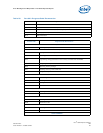
Table 22. LAN Connector LED status
LED Color LED State Condition
Left Green
Off LAN link is not established.
On LAN link is established.
Blinking LAN activity is occurring.
Right
N/A Off 10 Mbits/sec data rate is selected
Green On 100 Mbits/sec data rate is selected
Yellow On 1000 Mbits/sec data rate is selected