


Intel
®
IQ31244 Customer Reference Board
User’s Manual 19
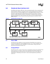
3.2 General-Purpose I/O Unit
The Intel
®
80321 I/O Processor has eight general-purpose I/O GPIO[7:0] pins to control or
monitor external devices in the I/O subsystem:
• The GPIO[0] and GPIO[1] signals are for CompactFlash* status.
• The GPIO[2] signal can be set to sound the buzzer. The buzzer can be disabled by adding a
jumper onto Z14.
• The Flash ROM signal VPEN is assigned to GPIO[4] to allow software connection for
code/data protection.
• The Flash ROM signal STS is assigned to GPIO[5] to allow interrupt input from the Flash
ROM.
• The GPIO[6] and GPIO[7] signals are for the I
2
C bus.
3.3 I
2
C Bus Units
The IQ31244 has two Inter-Integrated Circuit (I
2
C) bus units. The first I
2
C bus interfaces the Intel
®
80321 I/O Processor with the other I
2
C peripherals and microcontrollers for system management
functions. Both buses allow the processor to serve as a master and slave device residing on the I
2
C
bus. The first I
2
C has four components attached to the processor: the SDRAM EEPROM, the two
temperature sensors, and the reset supervisor (with I
2
C addresses as shown in Table 10). The
second I
2
C bus interface is through J15, a 4-pin header with pin 1 as SDA and pin 2 as SCL.
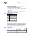
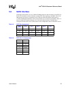
Table 9. GPIO Signal Definitions
GPIO Signal
7 Port 0 SCL
6 Port 0 SDA
5 Port 1 SCL/Flash_VPEN
4 Port 1 SDA/Flash_STS
3 Watchdog Timer
2Buzzer
1 Compact Flash Wait
0 Compact Flash Ready/Busy
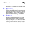
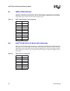
Table 10. I
2
C Device Addresses
Designator Device Function Address
J8
DDR SDRAM
EEPROM DIMM
Memory configuration 1010 0000
U35 LM75 Temperature sensor 1001 000x
U8 LM75 Temperature sensor 1001 001x
U7 ST-M41ST85W Reset supervisor 1101 000x